Check patentability & draft patents in minutes with Patsnap Eureka AI!

Magnetic resonance imaging apparatus and RF pulse control method

a magnetic resonance imaging and pulse control technology, applied in the field of magnetic resonance imaging, can solve the problems of ghosting or blurring, oscillation of intensity of echo signals, and often oscillation of artifacts, and achieve the effect of reducing the oscillation of echo signals and high quality

Active Publication Date: 2017-03-14
FUJIFILM HEALTHCARE CORP
View PDF14 Cites 0 Cited by
  • Summary
  • Abstract
  • Description
  • Claims
  • Application Information

AI Technical Summary

Benefits of technology

The present invention relates to a method for controlling RF pulses in an MRI apparatus to reduce echo signals and obtain high quality images without artifacts. The technical effect is that the method can provide high quality images even when the number of RF pulses in the start-up sequence is small.

Problems solved by technology

In a transient state, since the excitation and relaxation are not balanced and the spin is unstable, the intensity of echo signals often oscillates.
This oscillation often generates artifacts such as ghosts or blurring in reconstructed images.
While the α / 2 method can suppress oscillation of the spin having the same resonance frequency as the irradiation frequency of the RF pulse (hereinafter referred to as on-resonance spin), oscillation of the spin having the different resonance frequency from the irradiation frequency of the RF pulse (hereinafter referred to as off-resonance spin) cannot be sufficiently suppressed.

Method used


Image

  • Magnetic resonance imaging apparatus and RF pulse control method
  • Magnetic resonance imaging apparatus and RF pulse control method
  • Magnetic resonance imaging apparatus and RF pulse control method

Examples


embodiment 1

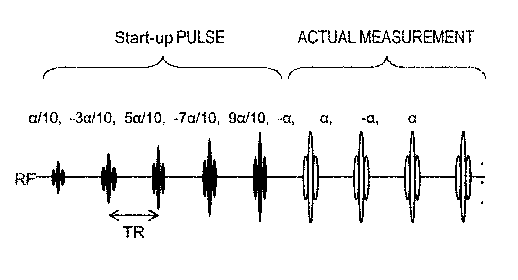
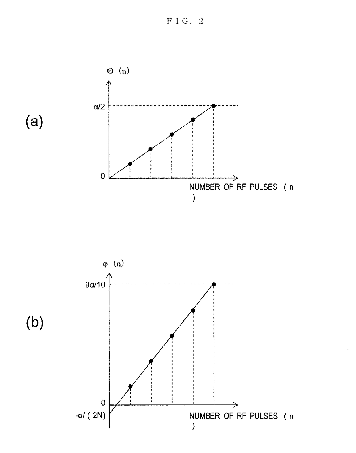
[0047]Next, the first embodiment of the MRI apparatus and the RF pulse control method related to the present invention will be described. The present embodiment controls the respective flip angles of the RF pulse sequence that forms the start-up sequence such that the offset (intercept) becomes the value which is other than 0 (zero) on the straight line. The present embodiment will be described below in detail referring to FIG. 2˜FIG. 9.

[0048]First, the outline of control in the present embodiment regarding the flip angle of the respective RF pulses in the start-up sequence will be described.

[0049]As shown in FIG. 2, sequence Θ(n) is created which linearly increases between 0 and α / 2. That is, the arithmetic progression is created with first term 0 and tolerance α / (2N).

Θ(n)=(α / (2N))×n(n=1,2, . . . ,N)  (2)

[0050]Here, α is the flip angle of the SSFP sequence at the time of collecting echo data, and N is the number of RF pulses in the start-up sequence. For example, when N is five tim...

embodiment 2

[0076]Next, the second embodiment of the MRI apparatus and the RF pulse control method of the present invention will be described. The present embodiment determines the respective flip angles in the RF pulse sequence of the start-up sequence using the sequence which changes smoothly at the start-up and the tangent point to the straight line of α / 2, i.e. the sequence in which the difference between the adjacent two terms monotonically increases and then monotonically decreases. The present embodiment will be described in detail referring to FIGS. 10 and 11.

[0077]While sequence Θ is created on the basis of the straight line which connects two points of 0 and α / 2 in the previously described first embodiment, the sequence can be generally created by any monotonically increasing sequence. Given this factor, as the result of numerical calculations by changing monotonically increasing sequences in various ways, the present inventor found that the oscillation of echo signals can be suppress...


PUM


Abstract

Disclosed are a magnetic resonance imaging apparatus and an RF pulse control method wherein an RF pulse sequence in a start-up sequence is set as a monotonically increasing flip angle with offset, in order to reduce ghosts, blurring, and other artifacts during measurement in a transient state. For example, the sum of two adjacent consecutive terms in a monotonically increasing sequence is set as the flip angle. Specifically, the number of RF pulses in the RF pulse sequence and the flip angle for the RF pulses in an SSFP sequence are set, and the monotonically increasing flip angle with offset is found, based on the set number of RF pulses in the RF pulse sequence and the flip angle for the RF pulses in the SSFP sequence, and used as the RF pulse sequence.

Description

FIELD OF THE INVENTION[0001]The present invention relates to a magnetic resonance imaging (hereinafter referred to as “MRI”) apparatus, particularly to a technique that controls application of high-frequency magnetic field pulses for rapidly leading the magnetization to a steady state free precession.DESCRIPTION OF RELATED ART[0002]An MRI apparatus is capable of measuring nuclear magnetic resonance (NMR) signals produced by atomic nuclear spins that form an object to be examined, particularly human tissue, and imaging shapes or functions of the head, abdomen, limbs and the like in a 2-dimensional or 3-dimensional manner. In this imaging, different phase encoding is given to the NMR signals according to the gradient magnetic field, and frequency encoding is also given to the NMR signals. The encoded NMR signals are measured as time-series data. The measured NRR signals are reconstructed as an image by 2-dimensional or 3-dimensional Fourier transform.[0003]In the above-described MRI a...

Claims


Application Information

Patent Timeline
Patent Type & Authority Patents(United States)
IPC IPC(8): G01R33/54G01R33/565G01R33/561G06F17/11
CPCG01R33/543G01R33/565G01R33/5613G06F17/11
Inventor NAKANISHIITAGAKI, HIROYUKI
Owner FUJIFILM HEALTHCARE CORP
Features
  • R&D
  • Intellectual Property
  • Life Sciences
  • Materials
  • Tech Scout
  • Unparalleled Data Quality
  • Higher Quality Content
  • 60% Fewer Hallucinations
Learn More