

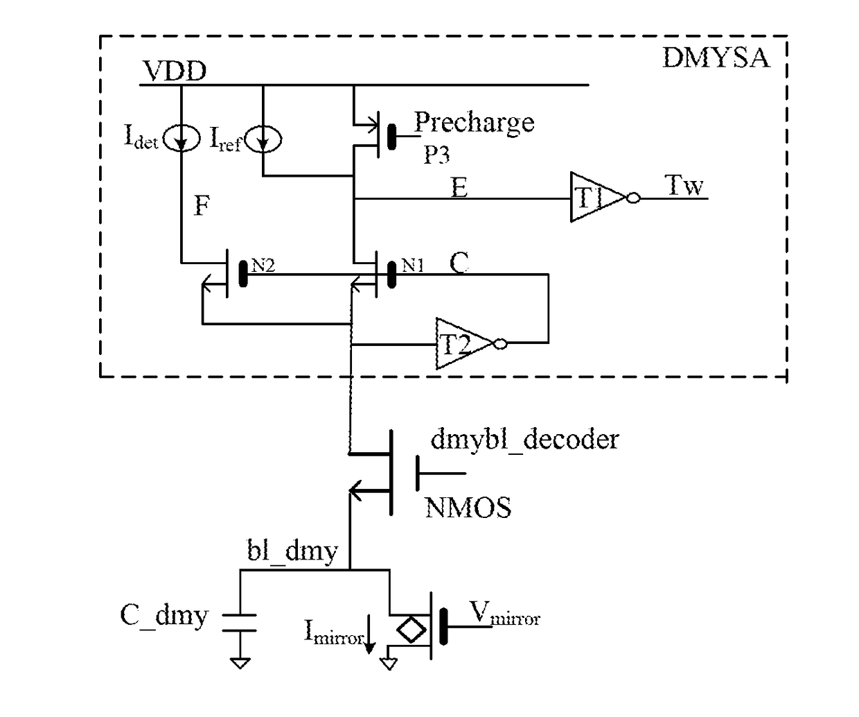
Circuits for control of time for read operation, using a current mirror circuit to mirror a reference current into the dummy device and generates time control signals based on the mirrored current
a technology of read operation and circuit, which is applied in the field of circuits for controlling the time for read operation, can solve the problems of not meeting the requirements of different test devices, inability to generate different sets of time control signals, etc., and achieves the effect of reducing the average energy consumed in read operation
- Summary
- Abstract
- Description
- Claims
- Application Information
AI Technical Summary
Benefits of technology
Problems solved by technology
Method used
Image

Examples
Embodiment Construction
[0025]Circuits for control of time for read operation according to the present invention will be described in greater detail in the following description which presents preferred embodiments of the invention, in conjunction with the accompanying drawings. It is to be appreciated that those of skill in the art can make changes in the invention disclosed herein while still obtaining the beneficial results thereof. Therefore, the following description shall be construed as being intended to be widely known by those skilled in the art rather than as limiting the invention.
[0026]For simplicity and clarity of illustration, not all features of the specific embodiments are described. Additionally, descriptions and details of well-known functions and structures are omitted to avoid unnecessarily obscuring the invention. The development of any specific embodiment of the present invention includes specific decisions made to achieve the developer's specific goals, such as compliance with system...
PUM
 Abstract
Description
Claims
Application Information