Buck converter with a variable-gain feedback circuit for transient responses optimization

a feedback circuit and variable-gain technology, applied in the field of buck converters, can solve the problems of degrading the signal-to-noise ratio (snr) performance of noise-sensitive circuits, reducing system reliability, and so as to achieve the effect of increasing chip area and power consumption

Inactive Publication Date: 2017-03-21
MEGAWIN TECH +1
View PDF25 Cites 15 Cited by
  • Summary
  • Abstract
  • Description
  • Claims
  • Application Information

AI Technical Summary

Benefits of technology

[0013]The buck converter is substantially a capacitor-current-controlled hysteretic buck converter, which is implemented to simultaneously optimize both a load transient response and a DVS transient response with insignificant increase of chip area and power consumption. Also, the optimized load transient response and DVS transient response are implemented for minimizing both output voltage undershoot / overshoot and settling time in the buck converter.

Problems solved by technology

However, if the transient responses of the buck converters are slow, a large output voltage undershoot / overshoot or a long settling time will occur, resulting in reduced reliability of the systems or degraded signal-to-noise ratio (SNR) performance of noise-sensitive circuits.
However, the chip area and power consumption will increase.
However, the aforementioned techniques for improving the controller can only achieve either fast load transient or fast DVS transient response.

Method used


Image

  • Buck converter with a variable-gain feedback circuit for transient responses optimization
  • Buck converter with a variable-gain feedback circuit for transient responses optimization
  • Buck converter with a variable-gain feedback circuit for transient responses optimization

Examples


Embodiment Construction

[0028]Reference will now be made to the drawing figures to describe the present disclosure in detail.

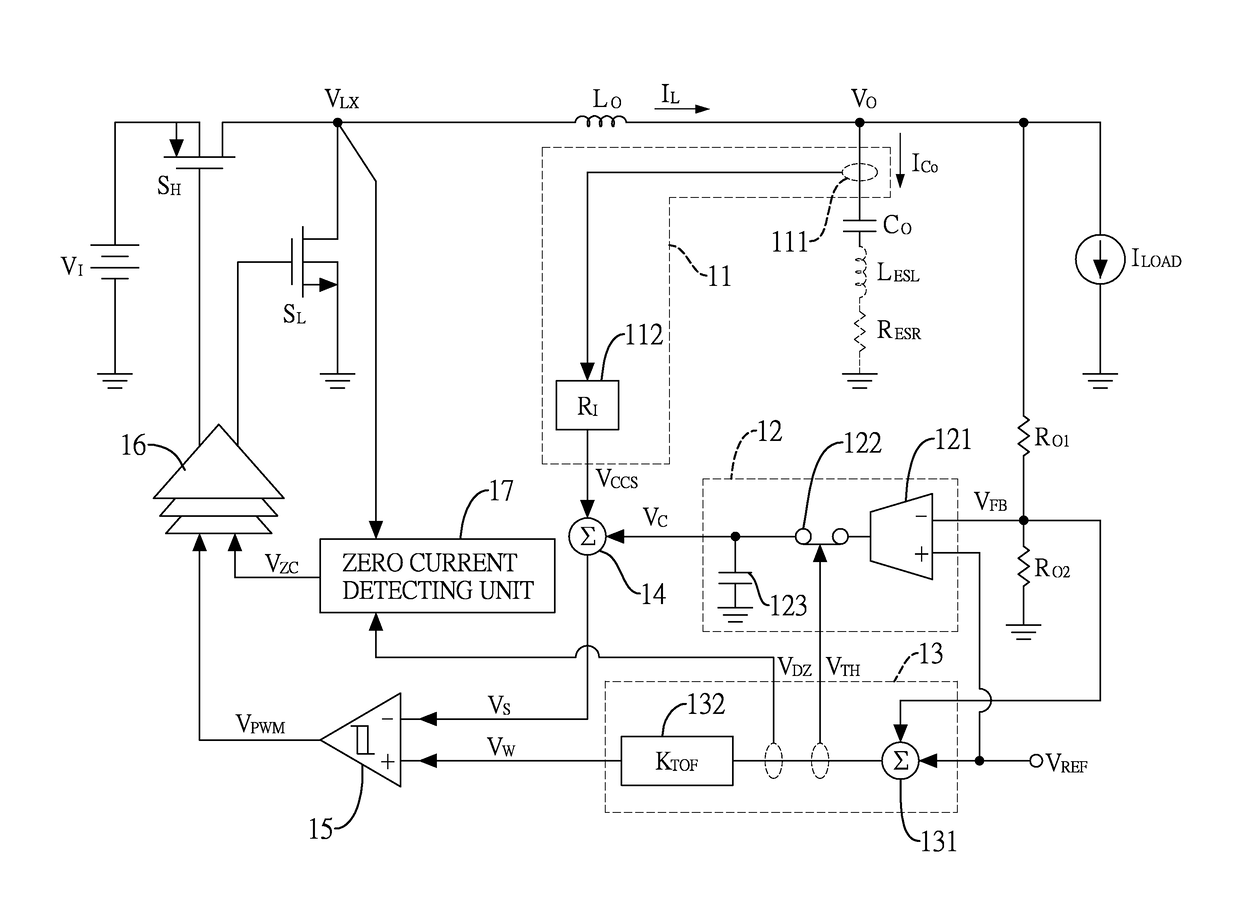
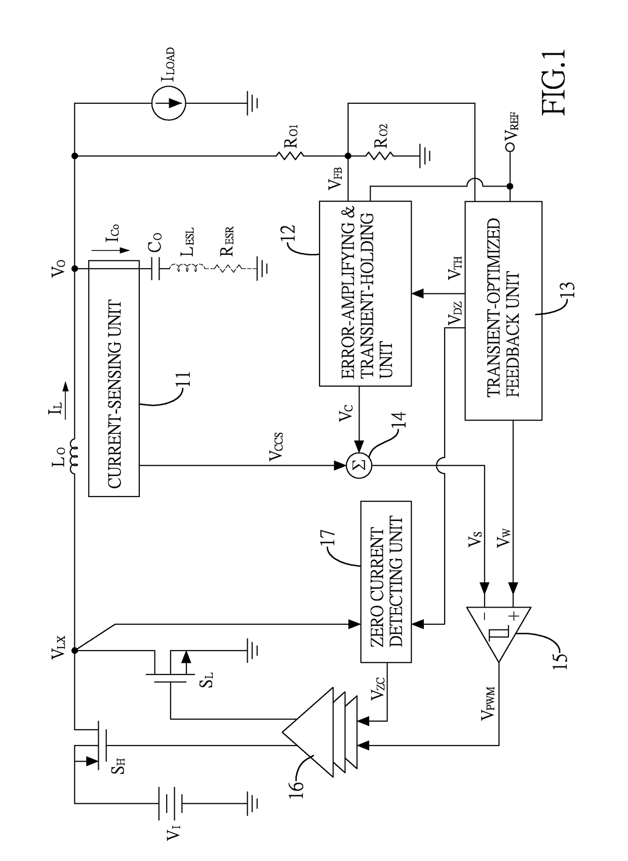
[0029]FIG. 1 shows a buck converter with a variable-gain feedback circuit for transient responses optimization. The buck converter includes a power stage circuit and a control circuit. The power stage circuit with an input side and an output side includes a pair of switches SH,SL, an output capacitor CO, and an output inductor LO. The switches SH,SL include a high-side switch SH and a low-side switch SL, both are electrically connected to an input voltage VI, which is a direct current (DC) voltage at the input side. In this example, the high-side switch SH is, but not limited to, a P-type MOSFET switch and the low-side switch SL is, but not limited to, an N-type MOSFET switch.

[0030]The output capacitor CO is electrically connected between the output side and a ground. In particular, the output capacitor CO is modeled with its parasitic inductance LESL and parasitic resistance RESR. T...


PUM


Abstract

A buck converter includes a power stage circuit and a control circuit. The power stage circuit has a pair of switches, an output inductor, and an output capacitor. The control circuit has a current-sensing unit (CCS), an error-amplifying (EA) and transient-holding (TH) unit, a transient-optimized feedback unit (TOF), and a PWM generation unit. The CCS senses an output capacitor current. The EA with the TH receives a feedback voltage and a reference voltage to generate an error signal. The TOF receives the feedback voltage and the reference voltage to generate a proportional voltage signal by a variable gain value. The PWM generation unit receives the proportional voltage signal and a sensing voltage signal to generate a PWM signal. When the proportional voltage signal equals the sensing voltage signal, the switches are controlled by the PWM signal at an optimal time point so that transient responses are optimized.

Description

BACKGROUND[0001]1. Technical Field[0002]The present disclosure relates generally to a buck converter, and more particularly to a buck converter with a variable-gain feedback circuit for transient responses optimization.[0003]2. Description of Related Art[0004]Switching buck converters are widely used as voltage regulators in battery-powered portable devices to achieve high power-conversion efficiency. FIG. 10 shows a block diagram of a conventional buck converter which includes a power stage and a controller. Also, FIG. 11A and FIG. 11B are schematic circuit diagrams respectively showing operations of a high-side ON state and a low-side ON state in FIG. 10. The synchronous topology of the buck converter has two switches, one is referred to as the high-side switch SH and the other is referred to as the low-side switch SL.[0005]The controller mainly has an error amplifier with compensation components 21, a pulse width modulation (PWM) generator 22, and a driver 23. The error amplifier...

Claims


Application Information

Patent Timeline
Patent Type & Authority Patents(United States)
IPC IPC(8): H02M3/158H02M1/00
CPCH02M3/158H02M2001/0009H02M1/0009H02M1/0025H02M1/0048Y02B70/10
Inventor HUNG, TING-HSUANHUANG, SZU-YUKUO, TAI-HAURWEN, KOW-LIANG
Owner MEGAWIN TECH
Why Eureka
Try Eureka