
Ceramic matrix composite material part

a ceramic matrix and composite material technology, applied in the field of ceramic matrix composite parts, can solve the problems of degrading the cmc material, cracking the matrix in practice, etc., and achieve the effect of improving the li

Active Publication Date: 2017-03-28
SAFRAN CERAMICS SA +1
View PDF16 Cites 0 Cited by
  • Summary
  • Abstract
  • Description
  • Claims
  • Application Information

AI Technical Summary

Benefits of technology

The sequenced interphase coating significantly increases the lifetime of CMC parts by diverting damage into the matrix, delaying oxidation, and maintaining mechanical strength in oxidizing environments.

Problems solved by technology

In CMC materials, cracking of the matrix is inevitable in practice, often as from fabrication.
Nevertheless, in utilization conditions under an oxidizing atmosphere and at high temperature, cracks propagating as far as the interphase provide paths giving access to oxygen, and the PyC or BN interphase can then oxidize, as indeed can the underlying fibers if they are made of carbon, thereby degrading the CMC material.

Method used


Image

  • Ceramic matrix composite material part
  • Ceramic matrix composite material part
  • Ceramic matrix composite material part

Examples


example 1

C Fibers, (BCpropane / SiC)×4 Interphase, Matrix of PyC, B4C, SiC, Si—B—C Type

[0062]Fiber preforms were obtained from a fabric made by multilayer weaving of carbon yarns. The weaving was performed with an interlock type weave so as to increase the delamination strength of the material that was finally obtained. Preforms were obtained by being cut out from the resulting multilayer fabric and by being held between two perforated plates of a graphite shaper so as to present a fiber volume fraction (i.e. the percentage of the apparent volume of the preform occupied by the fibers) generally lying in the range approximately 30% to 50%.

[0063]An interphase coating made up of boron-doped pyrolytic carbon layers alternating with SiC layers was made by conventional CVI on the fibers of the preforms. The coating made up of four BC / SiC bi-layers is written (BC / SiC)×4.

[0064]Each elementary layer of BC was deposited with a reaction gas containing a mixture of propane C3H8 and of boron trichloride BC...

example 2

C Fibers, (BCpropane / SiC)×4 Interphase, Matrix of BC, B4C, SiC, Si—B—C Type

[0071]The procedure was the same as in example 1, except for the sequenced matrix in which the pyrolytic carbon PyC of the crack-deflector layers was replaced with boron-doped carbon BC of a nature similar to that of the interphase coating.

example 3

C Fibers, PyCCH4 / SiC Interphase, Matrix of PyC, B4C, SiC, Si—B—C Type

[0072]The procedure was the same as in example 1, except for the interphase coating, which was of the PyC / SiC type formed by an elementary layer of PyC covered by an elementary layer of SiC. The elementary layer of PyC was obtained by conventional CVI with a gas in which the carbon precursor was natural gas, i.e. essentially methane. The target mean thicknesses for the layers of PyC and of SiC were respectively about 100 nm and about 1 μm, sufficient for consolidating the preforms.

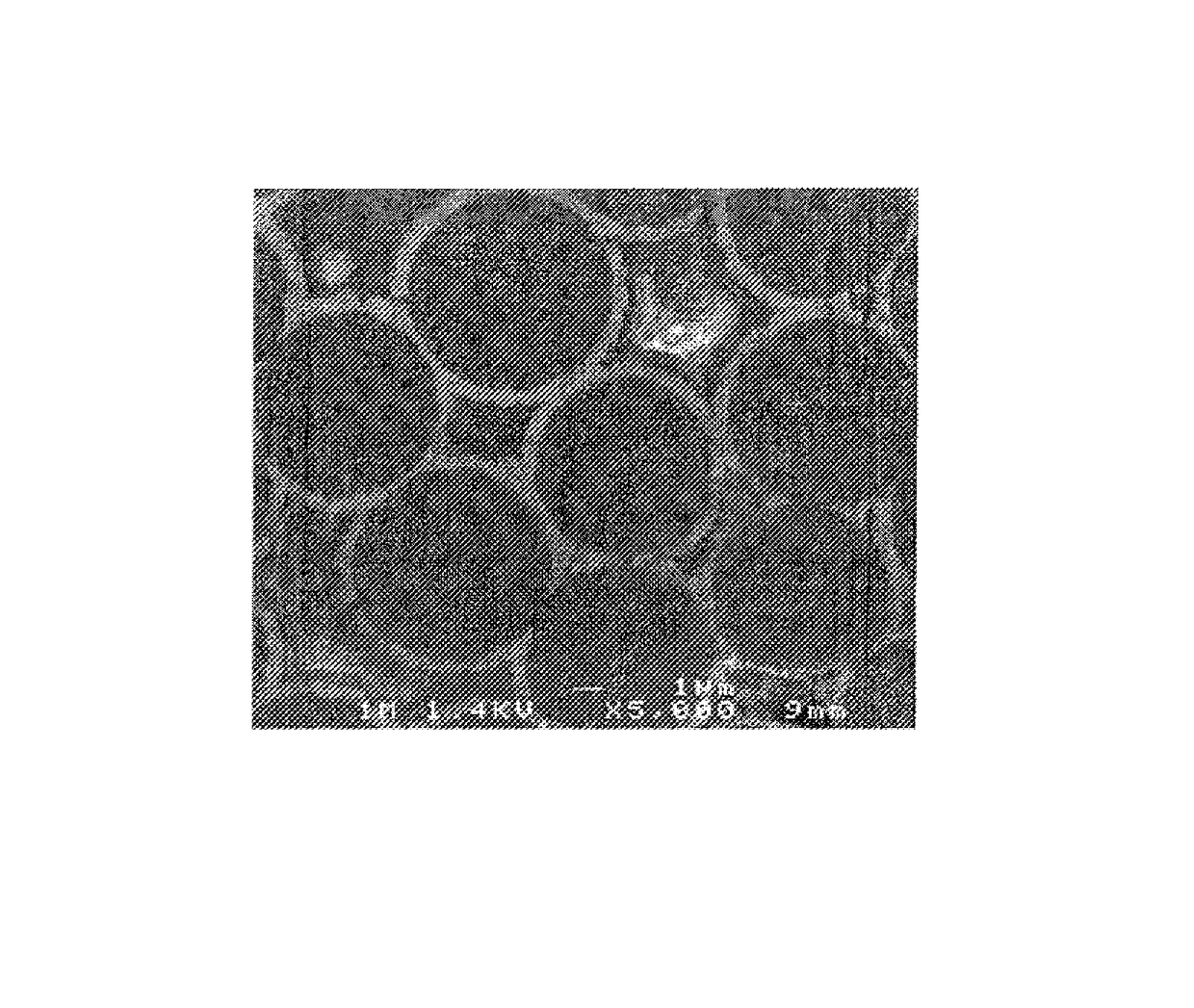
[0073]FIG. 4 shows that the elementary layer of SiC presents a relatively great surface roughness generated by the presence of coarse grains of SiC having a size greater than 50 nm.


PUM

PropertyMeasurementUnit
roughnessaaaaaaaaaa
roughnessaaaaaaaaaa
thicknessaaaaaaaaaa

Abstract

A part made of ceramic matrix composite material has fiber reinforcement of carbon or ceramic fibers and a majority-ceramic sequenced matrix having first matrix layers made of crack-deflector material alternating with second matrix layers made of ceramic material. An interphase coating is interposed between the fibers and the matrix, and the interphase coating adheres to the fibers and to the matrix, and is formed of at least one sequence constituted by a first elementary layer made of carbon, possibly doped with boron, surmounted by a second elementary layer made of ceramic. The outer elementary interphase layer of the coating is a ceramic layer having an outer surface formed by ceramic grains of size lying essentially in the range 20 nm to 200 nm, with the presence of grains of size greater than 50 nm conferring roughness on the outer surface ensuring mechanical attachment with the adjacent matrix phase.

Description

BACKGROUND OF THE INVENTION[0001]The invention relates to parts made of ceramic matrix composite (CMC) material. The term “CMC material part” is used herein to mean a part made of a material comprising fiber reinforcement made of carbon or ceramic fibers that has been densified by a matrix comprising at least a majority of ceramic.[0002]CMC material parts are used in various applications, in particular in the fields of aviation and space, where they are used because of their thermostructural properties, i.e. their capacity to constitute structural elements because of their mechanical strength, in particular in bending, in traction, and against impacts, which is much greater than that of solid ceramics, combined with their capacity to conserve this mechanical strength up to temperatures that are high, well above 1000° C.[0003]In CMC materials, cracking of the matrix is inevitable in practice, often as from fabrication.[0004]Proposals have been made to interpose an interphase coating ...

Claims


Application Information

Patent Timeline
Patent Type & Authority Patents(United States)
IPC IPC(8): C04B35/80C04B35/563C04B35/565C04B35/628B82Y30/00
CPCC04B35/806B82Y30/00C04B35/563C04B35/565C04B35/6286C04B35/62863C04B35/62873C04B35/62884C04B35/62894C04B35/62897C04B35/803C04B2235/3821C04B2235/3826C04B2235/5248C04B2235/614C04B2235/781C04B2235/96Y10T428/259C04B35/80
Inventor LAMOUROUX, FRANCKBERTRAND, SEBASTIENJACQUES, SYLVAINLOUCHET, CAROLINE
Owner SAFRAN CERAMICS SA
Learn More