Simulating effects of temperature on acoustic microwave filters

a technology of acoustic microwave filters and temperature simulation, applied in the field of microwave filters, can solve the problems of affecting the size and cost of resonators for a given, corresponding compromise in filter steepness or selectivity, and the inability to design or optimize acoustic filters consistently

Active Publication Date: 2017-03-28
MURATA MFG CO LTD
View PDF7 Cites 9 Cited by
  • Summary
  • Abstract
  • Description
  • Claims
  • Application Information

AI Technical Summary

Problems solved by technology

In particular, such electrical filters are used to select desired electrical signal frequencies from an input signal by passing the desired signal frequencies, while blocking or attenuating other undesirable electrical signal frequencies.
This requirement for low resistance tends to drive the size and cost of the resonators for a given technology.
In most filter technologies, achieving a low insertion loss requires a corresponding compromise in filter steepness or selectivity.
Thus, without an accurate model of the acoustic filter for the effects of temperature, the acoustic filter cannot be designed or optimized consistently.
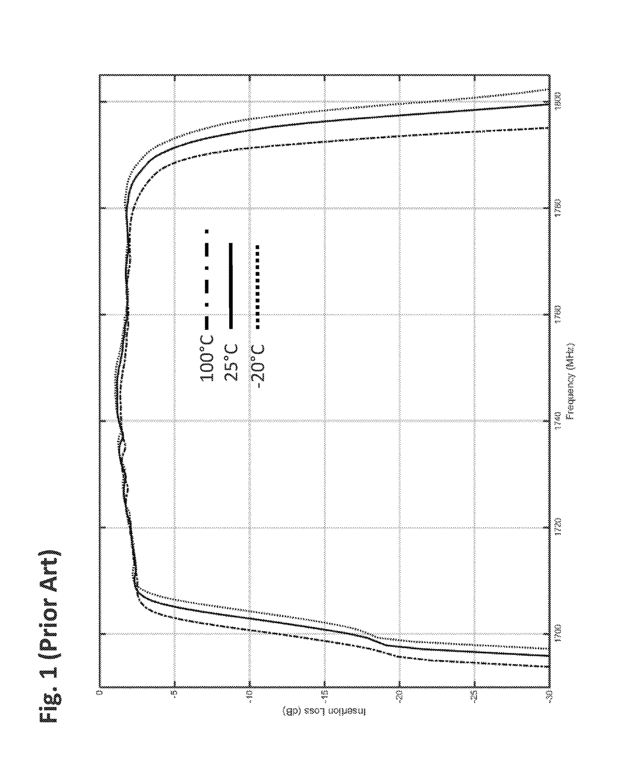
However, measurements of acoustic microwave filters show that this approach neglects the critical fact that the resonant and anti-resonant frequencies shift by different amounts for a given temperature change.
Therefore, this simple approach incorrectly predicts a bandwidth unchanged by temperature.
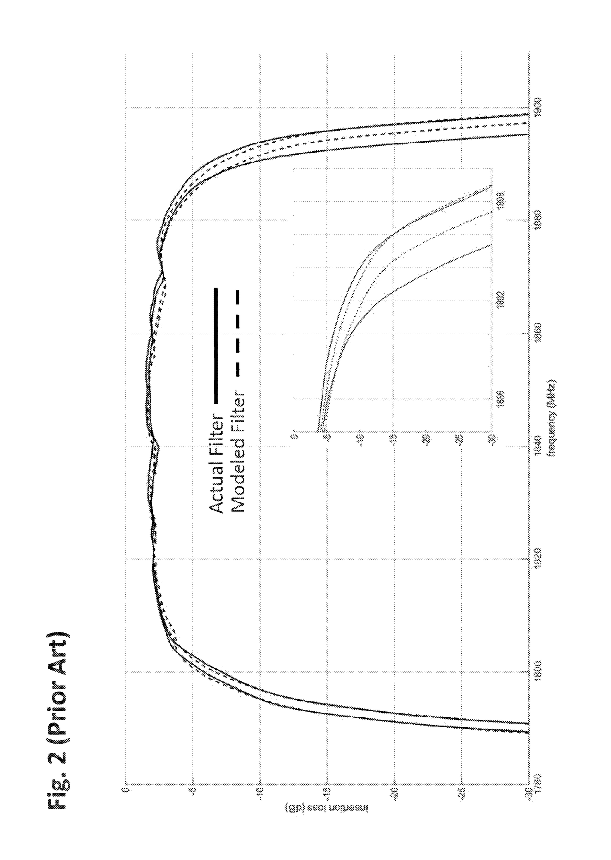
However, with as many parameters as are afforded in such a model, it is difficult to find a consistently predictive model.
In addition, the construction of such a model is time consuming and onerous.
Furthermore, the model may even be misleading, since the important frequency response of each resonator depends sensitively on the surrounding elements when embedded in a filter.
Thus, the primary difficulty with this sophisticated method is the faithful translation of the isolated resonator measurements to the same resonator's response once embedded in a filter or duplexer.

Method used


Image

  • Simulating effects of temperature on acoustic microwave filters
  • Simulating effects of temperature on acoustic microwave filters
  • Simulating effects of temperature on acoustic microwave filters

Examples


Embodiment Construction

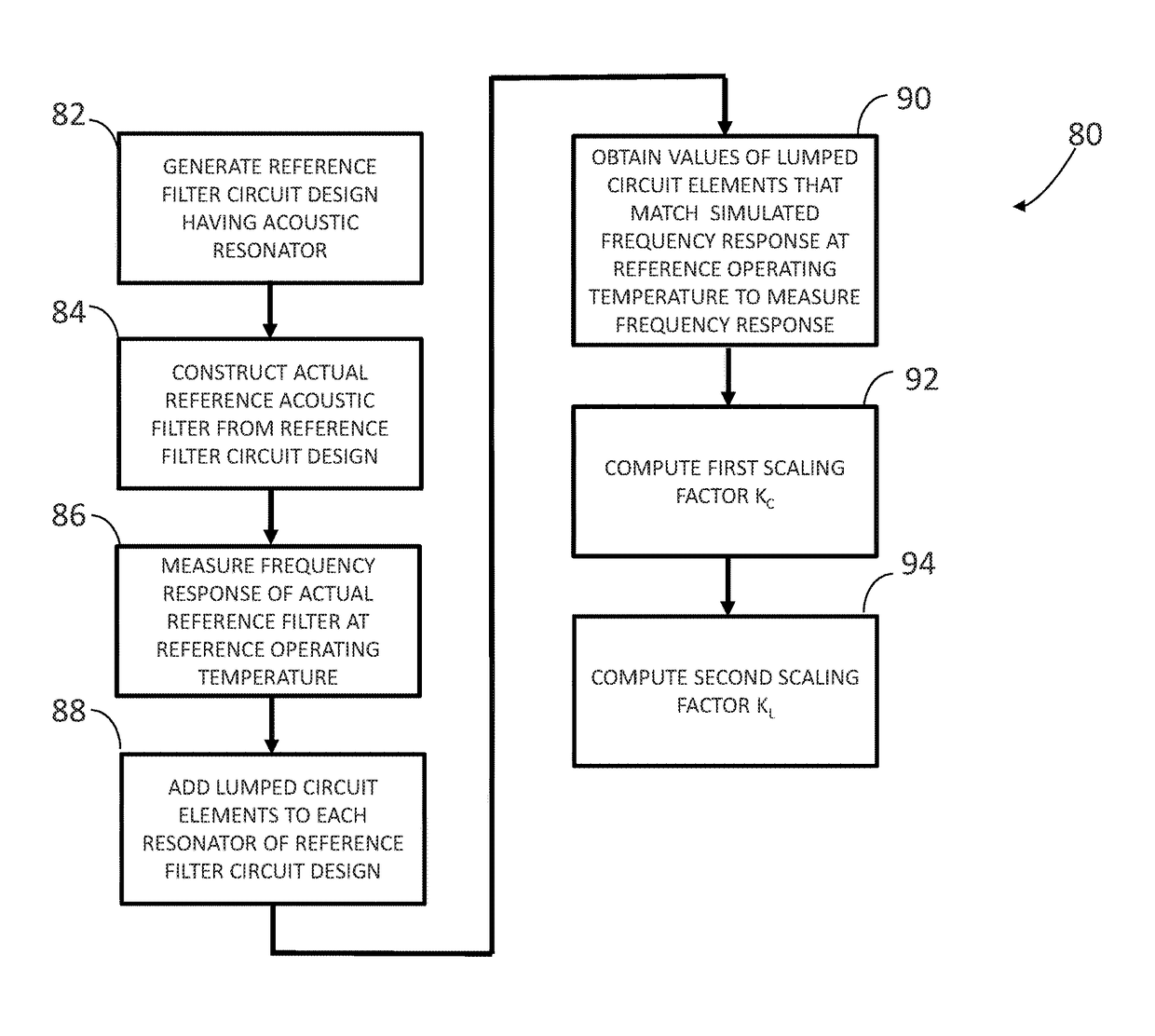
[0035]The present disclosure describes a technique for designing acoustic wave (AW) microwave filters (such as surface acoustic wave (SAW), bulk acoustic wave (BAW), film bulk acoustic resonator (FBAR), microelectromechanical system (MEMS) filters)). This technique can be applied to AW microwave filters in the 300 MHz to 300 GHz frequency range, particularly in the 300 MHz to 10.0 GHz frequency range, and even more particularly in the 500 MHz to 3.5 GHz frequency range. Such AW microwave filters may be either fixed frequency and / or tunable filters (tunable in frequency and / or bandwidth and / or input impedance and / or output impedance), and may be used for single band or multiple band bandpass filtering and / or bandstop. Such AW microwave filters are advantageous in applications that have demanding electrical and / or environmental performance requirements and / or severe cost / size constraints, such as those found in the radio frequency (RF) frontends of mobile communications devices, inclu...


PUM


Abstract

A method of designing an acoustic microwave filter comprises generating a proposed filter circuit design having an acoustic resonant element with a defined admittance value, introducing a lumped capacitive element in parallel and a lumped inductive element in series with the resonant element, selecting a first capacitance value for the capacitive element and a first inductance value for the inductive element, thereby creating a first temperature modeled filter circuit design, simulating the first temperature modeled filter circuit design at a first operating temperature, thereby generating a first frequency response, selecting a second capacitance value for the capacitive element and a second inductance value for the inductive element, thereby creating a second temperature modeled filter circuit design, simulating the second temperature modeled filter circuit design at a second operating temperature, thereby generating a second frequency response, and comparing the first and second frequency responses to the frequency response requirements.

Description

RELATED APPLICATION DATA[0001]The present application is continuation of U.S. patent application Ser. No. 14 / 941,462, filed Nov. 13, 2015. The foregoing application is hereby incorporated by reference into the present application in its entirety.FIELD OF THE INVENTION[0002]The present inventions generally relate to microwave filters, and more particularly, to acoustic microwave filters designed for narrow-band applications.BACKGROUND OF THE INVENTION[0003]Electrical filters have long been used in the processing of electrical signals. In particular, such electrical filters are used to select desired electrical signal frequencies from an input signal by passing the desired signal frequencies, while blocking or attenuating other undesirable electrical signal frequencies. Filters may be classified in some general categories that include low-pass filters, high-pass filters, band-pass filters, and band-stop filters, indicative of the type of frequencies that are selectively passed by the ...

Claims


Application Information

Patent Timeline
Patent Type & Authority Patents(United States)
IPC IPC(8): G06F17/50
CPCG06F17/5045G06F17/5009G06F2217/16G06F2217/80G06F17/504G06F17/5036H03H9/46H03H9/465H03H9/542H03H9/605H03H9/6483G06F30/36G06F30/367G06F30/30G06F2119/08H03H9/13H03H9/171H03H9/467H03H9/54G06F30/39G06F30/20G06F30/327G06F30/398G06F30/3323G06F2111/10G06F3/162H03H3/08H03H2003/0071
Inventor MCHUGH, SEANFENZI, NEAL O.
Owner MURATA MFG CO LTD
Why Eureka
Try Eureka