Ion-exchange equipment

a technology of ion-exchange equipment and equipment, which is applied in the direction of electrochemical generators, separation processes, water treatment, etc., can solve the problems of reducing power generation efficiency, smooth and efficient ion-exchange operation, and generating impurity ions, so as to reduce the pressure loss, and suppress the effect of pressure loss

Active Publication Date: 2017-04-04
ROKI CO LTD
View PDF9 Cites 1 Cited by
  • Summary
  • Abstract
  • Description
  • Claims
  • Application Information

AI Technical Summary

Benefits of technology

[0022]According to the present invention of the characters mentioned above, the following advantageous effects and / or function will be attainable.
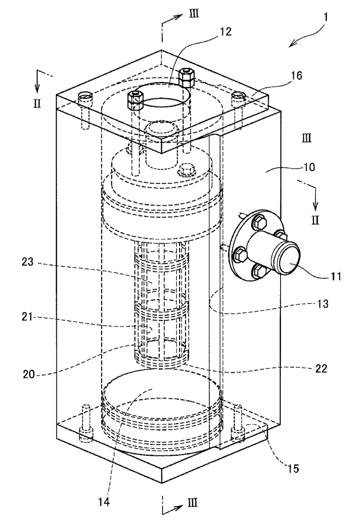
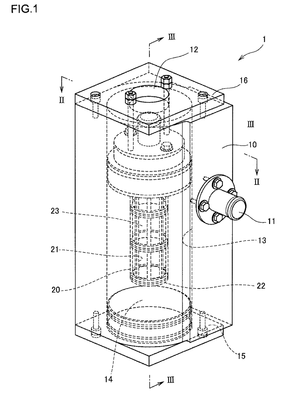
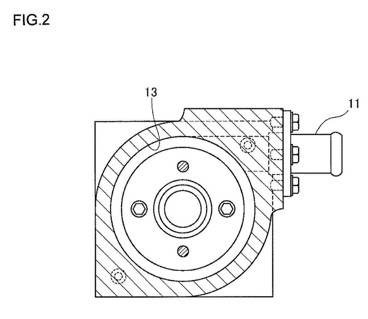
[0023]That is, in the ion-exchange equipment according to the present invention, the ion-exchange chamber extending along an axial direction of the tank unit has a circular cross section taken perpendicularly to the axial direction of the tank unit, and the cooling liquid flow-in port is formed so as to extend in a tangential direction of the ion-exchange chamber, and accordingly, the ion-exchange resin can revolve along the inner wall surface of the ion-exchange chamber by the flowing of the cooling liquid inside the ion-exchange chamber, and hence, the ion-exchange resin is not disproportionally present, thus the impurity ion being efficiently removed. Moreover, since the flow path of the cooling liquid can be sufficiently ensured, the pressure loss can be effectively suppressed.
[0024]Furthermore, according to the ion-exchange equipment of the present invention, since the cylindrical member is disposed in the ion-exchange chamber so as to extend axially, the flow path for the ion-exchange resin can be further ensured.
[0025]Still furthermore, in the ion-exchange equipment of the present invention, since a plurality of holes are formed to the peripheral wall surface, it becomes possible for the cooling liquid to flow out toward the flow-out port through these holes, the pressure loss can be further reduced.
[0026]Still furthermore, in the ion-exchange equipment of the present invention, since the cylindrical member is disposed in the ion-exchange chamber so as to face the bottom surface of the ion-exchange chamber with a predetermined distance therebetween, sufficient area of the peripheral wall surface can be ensured, thus further reducing the pressure loss.
[0027]Still furthermore, in the ion-exchange equipment of the present invention, since the cooling liquid flow-in port is disposed on an upper end side of the ion-exchange chamber, it becomes possible to elongate the cooling liquid flow path to thereby effectively remove the impurity ion.

Problems solved by technology

In such cooling circuit, there may cause a case of generating rust or like in the cooling circuit because of circulation of the cooling liquid, and as a result, impurity ion may be generated in the cooling liquid by such rust or by splitting reaction of the cooling liquid.
Further, it is known that such impurity ion raises electric conductivity of the cooling liquid, which may lead to such a problem as that electricity generated by the fuel cell leaks externally through the cooling liquid, and hence, power generation efficiency is decreased.
Further, since the ion-exchange resin does not move within the ion-exchange equipment, the cooling liquid hardly flows through the ion-exchange resin filling corner portions of the ion-exchanger equipment, which prohibits smooth and efficient ion-exchanging operation, thus being inconvenient.
However, according to the structure of the Patent Document 1, the floating plate is moved up and down inside the softening tank, there may cause a case in which abnormal noise is generated and the floating plate is damaged by abrasion.
More specifically, when a fuel cell provided with such ion-exchange equipment is mounted to an automobile, a fear of strength poverty in structure is considered by vibration during running of the automobile.
In addition, in a conventional ion-exchange equipment mounted on an automobile, since the ion-exchange resin fills a softening tank by applying pressure, it is difficult for cooling liquid to flow smoothly and to avoid increase of pressure loss.
Therefore, a fear that high load is applied to a pump for circulating the cooling liquid has been considered.

Method used


Image

  • Ion-exchange equipment
  • Ion-exchange equipment
  • Ion-exchange equipment

Examples


example

[0048]FIG. 5 is a graph representing an ion-exchange rate and a breakthrough rate between an example of the ion-exchange equipment 1 according to the embodiment of the present invention and a comparative example having a structure in which a conventional ion-exchange resin fills under pressure.

[0049]As is apparent from the graph of FIG. 5, in the example of the present invention, the ion-exchange resin could maintain the initial function and efficiency till the ion-exchange resin was broken through and the ion-exchange reaction proceeded till the breakthrough rate reached 100%.

[0050]On the other hand, in the comparative example, the ion-exchange resin could not maintain the initial efficiency till the ion-exchange resin was broken through and the efficiency of the ion-exchange reaction reduced before the breakthrough rate reached 100%. From this fact, it is found that the ion-exchange resin in the example of the present invention can efficiently remove the impurity in comparison wit...


PUM

PropertyMeasurementUnit
volumeaaaaaaaaaa
volumeaaaaaaaaaa
volumeaaaaaaaaaa

Abstract

An ion-exchange equipment includes a tank unit formed with a cooling liquid flow-in port and a cooling liquid flow-out port and provided therein with an ion-exchange chamber, and an ion-exchange resin in form of particles filling the ion-exchange chamber of the tank unit. The ion-exchange chamber is provided so as to extend along an axial direction of the tank unit and the ion-exchange chamber has a circular cross section taken perpendicularly to the axial direction of the tank unit, and the cooling liquid flow-in port is formed so as to extend in a tangential direction of the ion-exchange chamber.

Description

BACKGROUND OF THE INVENTION[0001]Field of the Invention[0002]The present invention relates to an ion-exchange equipment for removing impurity ion contained in a cooling liquid in a fuel cell system, for example.[0003]Description of the Related Art[0004]In a conventional technology concerning a fuel cell system, in order to cool a fuel cell that generates heat according to power generation, a cooling circuit is provided for forcibly circulating a cooling liquid by operating a pump. In such cooling circuit, there may cause a case of generating rust or like in the cooling circuit because of circulation of the cooling liquid, and as a result, impurity ion may be generated in the cooling liquid by such rust or by splitting reaction of the cooling liquid.[0005]Further, it is known that such impurity ion raises electric conductivity of the cooling liquid, which may lead to such a problem as that electricity generated by the fuel cell leaks externally through the cooling liquid, and hence, ...

Claims


Application Information

Patent Timeline
Patent Type & Authority Patents(United States)
IPC IPC(8): H01M8/04B01D15/18H01M8/04044B01J47/10C02F1/42B01J47/022C02F103/02
CPCH01M8/04044B01D15/18B01J47/022B01J47/10C02F1/42C02F2103/023C02F2201/003C02F2301/026C02F2303/08C02F2303/10Y02W10/30Y02E60/50
Inventor KAMO, KAORUSHIRAYANAGI, SATOSHIOGURA, MASAYA
Owner ROKI CO LTD
Why Eureka
Try Eureka