
Steel sheet for hot stamping member and method of producing same

a technology of hot stamping and steel sheets, which is applied in the direction of manufacturing tools, heat treatment equipment, and shaping tools, etc., can solve the problems of deterioration in shape fixability, difficult to obtain desired shape, and no examples of investigating steel sheets for hot stamping, etc., to achieve small defects, increase the application range of hot stamping components, and reduce the possibility of defects

Active Publication Date: 2017-04-11
NIPPON STEEL CORP
View PDF52 Cites 10 Cited by
  • Summary
  • Abstract
  • Description
  • Claims
  • Application Information

AI Technical Summary

Benefits of technology

This patent describes a steel sheet used for hot stamping that reduces the deflection of long formed products, resulting in less potential defects when joining with other components. The steel sheet also includes layers for improved corrosion resistance and surface quality, and can be produced using existing iron-making equipment. Additionally, the method of producing the steel sheet improves its performance. Overall, this patent expands the application range of hot stamping and enhances the quality of the finished product.

Problems solved by technology

In such an increase in the amount of a high-strength steel sheet used, the most significant problem is a phenomenon called “deterioration in shape fixability” which is inevitably caused when the strength of a steel sheet increases.
“Deterioration in shape fixability” refers to the general term for a phenomenon in which the spring-back amount after forming increases along with an increase in strength; and thus, the desired shape is difficult to obtain.
However, there are no examples of investigating a steel sheet for hot stamping from this point of view.
However, there are no examples of investigating a method of producing a steel sheet for hot stamping from this point of view.

Method used


Image

  • Steel sheet for hot stamping member and method of producing same
  • Steel sheet for hot stamping member and method of producing same
  • Steel sheet for hot stamping member and method of producing same

Examples


example 1

[0122]Steel pieces (steels) having chemical components as shown in Table 1 were obtained through steelmaking and casting. These steels were subjected to hot rolling, in which heating was performed to 1250° C. and a finish temperature was 910° C., and were coiled at a coiling temperature of 620° C. As a result, hot-rolled steel sheets having a thickness of 3.2 mm were obtained. These hot-rolled steel sheets were pickled and were cold-rolled. As a result, cold-rolled steel sheets having a thickness of 1.6 mm were obtained.

[0123]The above-described cold-rolled steel sheets were annealed for recrystallization under conditions shown in Table 2 to obtain steel sheets for hot stamping.

[0124]Under the condition x, a cold-rolled steel sheet was heated from 300° C. to 600° C. at a constant heating rate of 10° C. / s and then was heated to 800° C. at a constant heating rate of 2° C. / s. In this case, in both temperature ranges of from 300° C. to 600° C. and from 600° C. to 800° C., changes d / dt (...

example 2

[0137]Steel pieces (steels) having chemical components as shown in Table 4 were obtained through steelmaking and casting. These steels were treated under the same conditions as those of Example 1 to obtain hot-rolled steel sheets having a thickness of 3.0 mm. These hot-rolled steel sheets were pickled and were cold-rolled. As a result, cold-rolled steel sheets having a thickness of 1.2 mm were obtained.

[0138]These cold-rolled steel sheets were annealed for recrystallization under the conditions i, vii, and ix shown in Table 2 to obtain steel sheets for hot stamping.

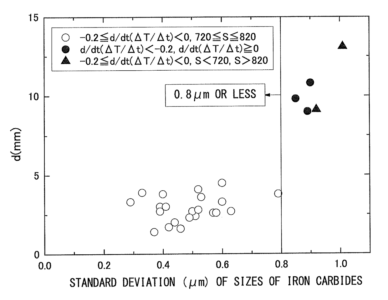
[0139]Sizes of iron carbides which were contained in a region from a surface of the obtained cold-rolled steel sheet to a position which was distant from the surface of the steel sheet by 0.3 mm in the thickness direction (a ¼ thickness position of the steel sheet) were measured, and a standard deviation of the sizes of iron carbides was obtained. In addition, the above-described cold-rolled steel sheets were hot-stamped ...

example 3

[0145]Steel pieces (steels) having chemical components as shown in Table 6 were obtained through steelmaking and casting. These steels were treated under the same conditions as those of Example 1 to obtain hot-rolled steel sheets having a thickness of 2.5 mm. These hot-rolled steel sheets were pickled and were cold-rolled. As a result, cold-rolled steel sheets having a thickness of 1.2 mm were obtained.

[0146]These cold-rolled steel sheets were heated to 800° C. according to a temperature history illustrated in FIG. 7, were immediately cooled at an average cooling rate of 6.5° C. / s, and were dipped in a molten Al bath (containing 10% of Si and unavoidable impurities) at 670° C. Then, the cold-rolled steel sheets were taken out from the molten Al bath after 5 seconds. The deposit amount of a plating layer was adjusted using a gas wiper, followed by air cooling to room temperature.

[0147]When the steel sheet temperature and the time after the start of annealing (time elapsed after the s...


PUM

PropertyMeasurementUnit
thicknessaaaaaaaaaa
thicknessaaaaaaaaaa
thicknessaaaaaaaaaa

Abstract

A steel sheet for a hot stamping member contains, as a chemical composition, 0.10 mass % to 0.35 mass % of C; 0.01 mass % to 1.0 mass % of Si; 0.3 mass % to 2.3 mass % of Mn; 0.01 mass % to 0.5 mass % of Al; limited to 0.03 mass % or less of P; limited to 0.02 mass % or less of S; limited to 0.1 mass % or less of N; and a balance consisting of Fe and unavoidable impurities, in which a standard deviation of diameters of iron carbides which are contained in a region from a surface to a ¼ thickness position of the steel sheet is less than or equal to 0.8 μm.

Description

TECHNICAL FIELD[0001]The present invention relates to a steel sheet for a hot stamping member capable of being desirably used for hot stamping which is a forming method of obtaining a high-strength member; and a method of producing the same.[0002]Priority is claimed on Japanese Patent Application No. 2011-100019, filed on Apr. 27, 2011, and the contents of which are incorporated herein by reference.BACKGROUND ART[0003]In the field of automobiles, construction machines, and the like, there has been intense research in how to reduce mass using a high-strength material. For example, in the automobile field, the amount of a high-strength steel sheet used has steadily increased for the purposes of suppressing an increase in the mass of a vehicle, which is required for securing collision safety and realizing high performance, and improving fuel efficiency to reduce carbon dioxide emissions.[0004]In such an increase in the amount of a high-strength steel sheet used, the most significant pr...

Claims


Application Information

Patent Timeline
Patent Type & Authority Patents(United States)
IPC IPC(8): B32B15/10C22C38/50C23C2/02C23C2/06C23C2/12C23C2/28C23C2/40C22C38/54B21D22/02B21D37/16C22C38/00C22C38/02C22C38/04C22C38/06C22C38/08C22C38/12C22C38/14C22C38/16C22C38/28C22C38/32B32B15/01C21D8/02C22C38/22C22C38/24C22C38/26C22C38/42C21D1/673
CPCC22C38/54B21D22/022B21D37/16B32B15/012B32B15/013C21D8/0247C21D8/0273C22C38/001C22C38/002C22C38/02C22C38/04C22C38/06C22C38/08C22C38/12C22C38/14C22C38/16C22C38/22C22C38/24C22C38/26C22C38/28C22C38/32C22C38/42C22C38/50C23C2/02C23C2/06C23C2/12C23C2/28C23C2/405C21D1/673Y10T428/12757Y10T428/12799C23C2/29C23C2/024C23C2/0224
Inventor TANAHASHI, HIROYUKIMAKI, JUN
Owner NIPPON STEEL CORP
Learn More