System and equipment for dispensing a high pressure compressed gas using special hydraulic fluid, semitrailer comprising vertical or horizontal gas cylinders

a technology of hydraulic fluid and high pressure compressed gas, which is applied in the direction of mechanical equipment, gas/liquid distribution and storage, vessel construction details, etc., can solve the problems of increasing process cost, high cost, and technical problems of gas liquefying process, so as to improve system performance, improve system performance, and improve system performance

Active Publication Date: 2017-04-11
NEOGAS DO BRASIL GAS NATURAL COMPRIMIDO
View PDF11 Cites 7 Cited by
  • Summary
  • Abstract
  • Description
  • Claims
  • Application Information

AI Technical Summary

Benefits of technology

[0023]The present invention refers to a complete system of transport and compression through an HPU (Hydraulic Pressurization Unit) that is connected with a gas container, a STV (semitrailer vehicle), which can comprise vertical or horizontal gas cylinders adapted to use of technology developed to keep the pressure constant in the cylinders of the semitrailer during the fueling operation. The invention consists of a simplified system and hydraulic pressurization equipment. The here disclosed oil filling system, oil return system and reduced number of pneumatically actuated valves provides an easy and fast control of the system by synchronizing the start thereof, which improves the system performance having more accurate response to the control actions. The simplified control system also reduces the maintenance problems.
[0024]In the gas pressurization system already known, the oil filling and return of a HPU for STV is performed in two lines, one for sending the oil and other for return the oil, as taught in PI0603687-2 patent document. Each pallet is a set of cylinders interconnected by pipes, which requires a manual shut-off valve and two compressed air actuated valves. Therefore, the system comprises many valves, which requires a significant portion of space in each pallet to accommodate all valves, reducing the space available to receive the cylinders and consequently, reducing the capacity of gas transport.

Problems solved by technology

However, the gas liquefying process presents technical problems.
Although being a well known technology, it requires the use of specific materials, which has a higher cost due to the extremely low temperature condition of the process.
This increases the process cost.
Another disadvantage is that the cost for producing liquefied natural gas (LNG) is proportionally too expensive in view of the produced LNG, such that, as less is the production of a LNG facility as higher is the production cost (US$ / m3 of produced LNG).
This affects the application of the cryogenic technology for producing reduced amounts of LNG.
Although a promising technique, ANG is not commercially used, as it is still matter of research.
However the solution proposed by Galileu is dangerous, as it is needed move pallets, which are too heavy.
The fractionated supply using cylinder pallets also has operational difficulties on the compression station.
The use of such system reduces the amount of transported cylinders, decreasing the transported gas volume and increasing the cost per m3 of transported gas.
The tracer element has a high cost and a maintenance of difficult execution, as it is inside the cylinder.
Besides the difficult maintenance of the disc, the use of the fitting may increase the chances of forming an emulsion, i.e., a friction between the oil and the gas.
The use of the fitting also results in a reduced flow rate, increasing the time of dispensing or refueling the gas.
When using a relief valve to maintain a pressure of 24.8 MPa, the compressing system requires the use of a specific type of cylinder, limiting the pressure and restricting the use of the system.
In this type of system there is high energy consumption.
However, the system presents the drawback of comprising a complex driving system of valves of high cost.
Therefore, the system comprises many valves, which requires a significant portion of space in each pallet to accommodate all valves, reducing the space available to receive the cylinders and consequently, reducing the capacity of gas transport.

Method used


Image

  • System and equipment for dispensing a high pressure compressed gas using special hydraulic fluid, semitrailer comprising vertical or horizontal gas cylinders
  • System and equipment for dispensing a high pressure compressed gas using special hydraulic fluid, semitrailer comprising vertical or horizontal gas cylinders
  • System and equipment for dispensing a high pressure compressed gas using special hydraulic fluid, semitrailer comprising vertical or horizontal gas cylinders

Examples


Embodiment Construction

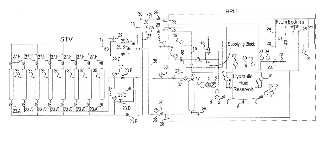
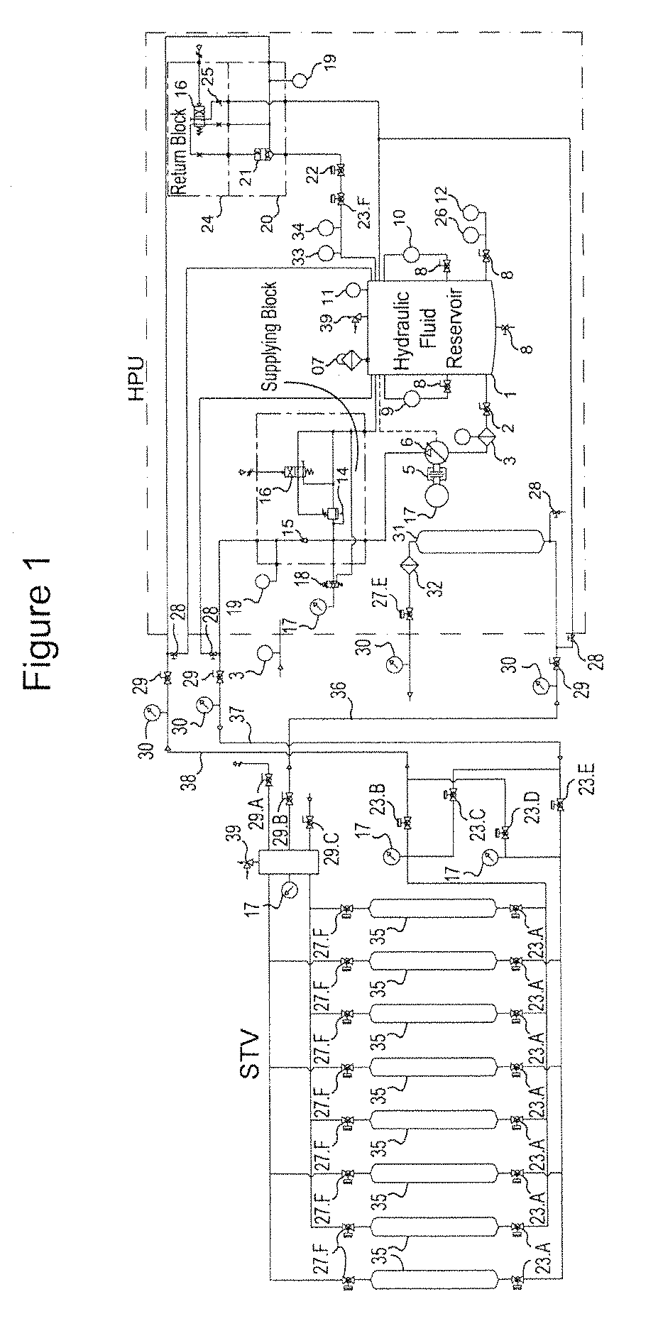
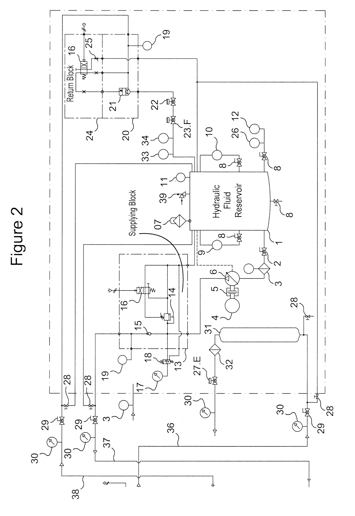
[0039]The invention will be described in reference to FIGS. 1 to 6, as follows.

[0040]HPU is a module of hydraulic high pressure generation using a hydraulic fluid of special composition, which is interconnected with a movable container comprising vertical or horizontal cylinders to supply natural gas to a customer. HPU has multiple flows according to the available supply need.

[0041]

Oil rateNG rateRequired energyHPUliters / minuem3 / hKwh / m320013.52150.02835021.53420.027600345390.027800457200.027105067.4210800.0281600101.416180.028220014022470.028Note:m3 at 20° C. and 1 atm.

[0042]The whole system has a number safety devices, including redundant safety devices. All cylinders have safety devices for exceeding pressure and temperature. The high pressure oil line has a pressure relief valve.

[0043]The entire system is designed according to strict security criteria. The suction and oil discharge lines are designed for 350 bar, although they operate with a much lower pressure.

[0044]This technol...


PUM


Abstract

The present invention relates to a system and equipment for dispensing a high pressure compressed gas using a special hydraulic fluid, comprising a hydraulic pressurization unit also known as “HPU”, which can be connected to a semi-trailer comprising compressed gas cylinders, upper and lower open ends, comprising a single valve arranged at the upper end of the cylinders, which supplies the compressed gas to a customer, one valve disposed at the lower end of the cylinders for both supplying of the hydraulic oil from an oil reservoir to the cylinders, and the return of the hydraulic oil to the hydraulic fluid reservoir from the cylinders.

Description

BACKGROUND[0001]Field[0002]The invention refers to a system and equipment to allow the transport and delivery of natural gas to a station or areas not supplied by gas pipelines. The invention combines a storage system and a hydraulic pressure system to allow transferring up to 95% of the stored gas from a storage cylinder to the customer with a pressure constant up to the end of the dispensing process.[0003]Description of the Related Art[0004]There are many known ways to transport natural gas. Due to its physical characteristics, natural gas does not liquefy even at high pressures. So, the natural gas transported at high pressure will be only at gaseous phase. Consequently, the relation of pressure parameters and the volume to be transported is very important for an economic gas transportation service. All materials of the construction must be specific for high pressure conditions and electrically classified areas.[0005]Cryogenics is also used for gas transportation. In the case, th...

Claims


Application Information

Patent Timeline
Patent Type & Authority Patents(United States)
IPC IPC(8): F17C5/06
CPCF17C5/06F17C2221/033F17C2223/0123F17C2225/0123F17C2227/0192F17C2250/0443F17C2260/02F17C2270/01F17C2201/032F17C2201/035F17C2205/0142F17C2205/0146F17C2205/0332F17C2223/036F17C2225/036F17C2250/032F17C2270/0168F17C2270/0171
Inventor GOUV A, CARLOS PEREIRAFLORES DE ALMEIDA, VAGNER
Owner NEOGAS DO BRASIL GAS NATURAL COMPRIMIDO
Why Eureka
Try Eureka