Switching power-supply circuit

a power supply circuit and power supply circuit technology, applied in the direction of electric variable regulation, process and machine control, instruments, etc., can solve the problems of complex power supply devices, difficult to reduce size and/or weight, and achieve the effect of reducing or preventing the occurrence of switching loss, reducing or preventing the voltage rise of output voltage, and small siz

Active Publication Date: 2017-04-11
MURATA MFG CO LTD
View PDF35 Cites 11 Cited by
  • Summary
  • Abstract
  • Description
  • Claims
  • Application Information

AI Technical Summary

Benefits of technology

[0034]With this configuration, in a light load, the conduction time-period of the rectifier switch element is controlled and the voltage rise of the output voltage is significantly reduced or prevented. In addition to this, in a heavy load, the turn-off of the rectifier switch element is performed with a zero current (i.e., with a ZCS operation). Therefore, the occurrence of a switching loss is significantly reduced or prevented.
[0035]According to various preferred embodiments of the present invention, it is possible to provide a small-sized and low-cost switching power-supply circuit whose circuit configuration is simplified while maintaining a high degree of accuracy in the output voltage of a second output portion.

Problems solved by technology

As a result of these required circuits, a power-supply device is complicated and it is difficult to reduce the size and / or weight thereof.

Method used


Image

  • Switching power-supply circuit
  • Switching power-supply circuit
  • Switching power-supply circuit

Examples


first preferred embodiment

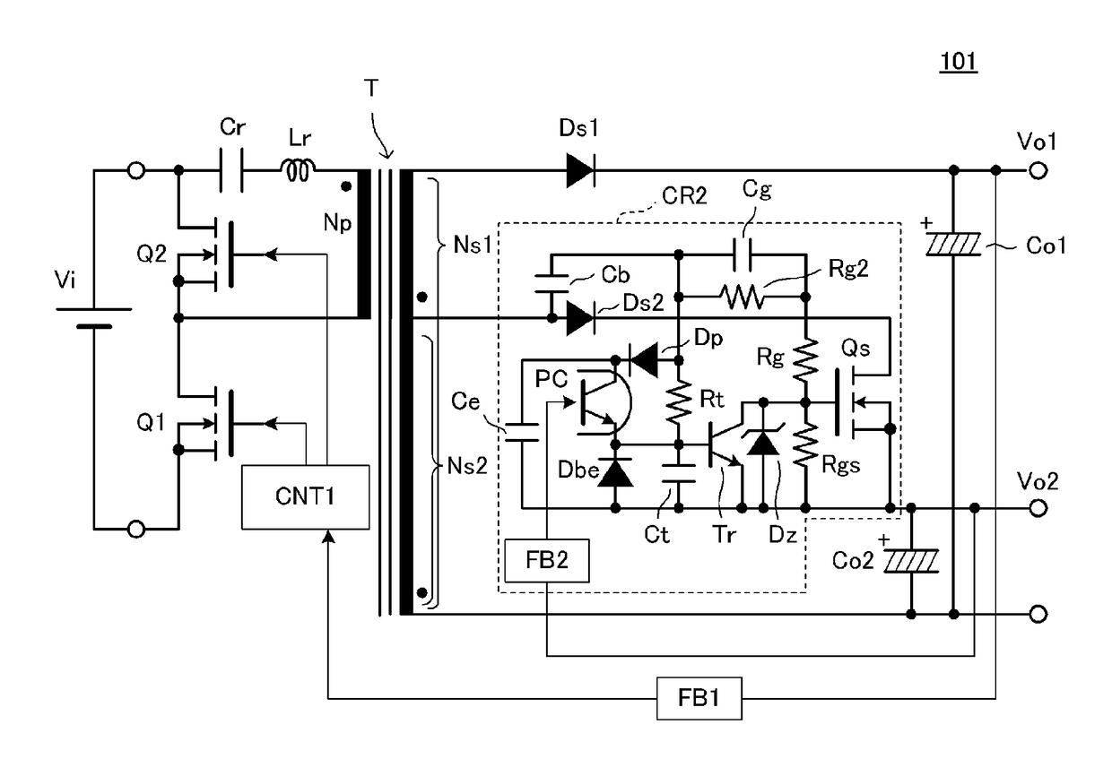
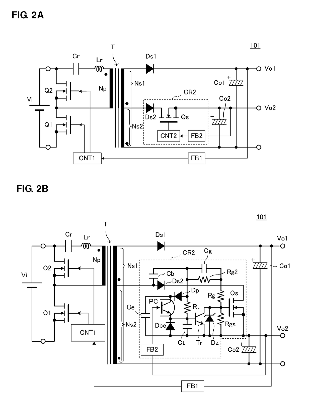
[0043]FIGS. 2A and 2B are the circuit diagrams of a switching power-supply circuit 101 according to a first preferred embodiment of the present invention. FIG. 3 is a main waveform diagram illustrating the operation of the switching power-supply circuit 101.

[0044]The switching power-supply circuit 101 includes a transformer T including a primary winding Np, a first secondary winding Ns1, and a second secondary winding Ns2, a first switching element (a main switching element) Q1 connected in series to the primary winding Np, a second switching element Q2 connected to a position providing a closed loop in combination with the primary winding Np, a first switching control circuit CNT1 alternately turning on and turning off the first switching element Q1 and the second switching element Q2 with a short dead time provided therebetween, and a first feedback circuit FB1. On the primary side of the transformer T, a resonance inductor Lr and a resonance capacitor Cr are provided in series wi...

second preferred embodiment

[0092]FIG. 4 is the circuit diagram of the main portion of a switching power-supply circuit 102 according to a second preferred embodiment of the present invention. In FIG. 4, only a circuit connected to the second secondary winding Ns2 of a transformer T is illustrated. A circuit connected to the primary winding and the first secondary winding of the transformer T is preferably the same or substantially the same as the circuit illustrated in FIG. 2B in the first preferred embodiment.

[0093]In the second preferred embodiment, a PNP transistor Tr2 is connected between the gate and source of a rectifier switch element Qs, and an NPN transistor Tr1 used for a small signal is connected to this transistor Tr2.

[0094]According to the second preferred embodiment, an ability to drive the rectifier switch element Qs is high, and as a result of a high amplification factor provided by two-stage transistors, it is possible to reliably turn off the rectifier switch element Qs. The other functions ...

third preferred embodiment

[0095]FIG. 5 is the circuit diagram of the main portion of a switching power-supply circuit 103 according to a third preferred embodiment of the present invention. In FIG. 5, only a circuit connected to the second secondary winding Ns2 of a transformer T is illustrated. A circuit connected to the primary winding and the first secondary winding of the transformer T is preferably the same or substantially the same as the circuit illustrated in FIG. 2B in the first preferred embodiment.

[0096]In the third preferred embodiment, a boot diode Db that directly charges a boot capacitor Cb is provided.

[0097]According to the third preferred embodiment, charging impedance (charging time constant) to the boot capacitor Cb is small, and it is possible to charge the boot capacitor Cb in a short charging time. The other functions are the same or substantially the same as the first preferred embodiment.


PUM


Abstract

A switching power-supply circuit includes a second rectifying/smoothing circuit arranged to generate a second output voltage by rectifying and smoothing the output of a second secondary winding, and the second rectifying/smoothing circuit includes a second rectifier circuit and a capacitor, connected to the second secondary winding. A second switching control circuit operates in response to an alternating-current winding voltage occurring in the second secondary winding, and includes a time constant circuit causing a switch mechanism connected to the control terminal of a rectifier switch element to operate, and a second feedback circuit arranged to detect and feed back the second output voltage to the time constant circuit.

Description

BACKGROUND OF THE INVENTION[0001]1. Field of the Invention[0002]The present invention relates to a switching power-supply circuit that outputs a voltage from each of a plurality of output portions, and in particular, to a switching power-supply circuit including a circuit that stabilizes the output voltage of a second output portion, in addition to a feedback circuit that feedback-controls a primary side in accordance with the output voltage of a first output portion.[0003]2. Description of the Related Art[0004]In International Publication No. WO2006 / 061924 Japanese Unexamined Patent Application Publication No. 3-7062, and Japanese Unexamined Patent Application Publication No. 2000-217356, switching power-supply circuits are disclosed each of which outputs a voltage from each of a plurality of output portions. In any one of International Publication No. WO2006 / 061924 Japanese Unexamined Patent Application Publication No. 3-7062, and Japanese Unexamined Patent Application Publication...

Claims


Application Information

Patent Timeline
Patent Type & Authority Patents(United States)
IPC IPC(8): H02M3/335
CPCH02M3/33507H02M3/33553H02M3/33561H02M3/33576Y02B70/10H02M1/08H02M3/33523H02M1/0054
Inventor HOSOTANI, TATSUYAYAMAGUCHI, SATOSHI
Owner MURATA MFG CO LTD
Why Eureka
Try Eureka