Method for automatically identifying instruments during medical navigation

a technology for automatically identifying instruments and medical navigation, applied in medical science, surgical navigation systems, sensors, etc., can solve the problems of inaccurate production and cost-effective use of instruments provided with marker elements, and achieve the effect of avoiding errors

Active Publication Date: 2017-04-18
BRAINLAB
View PDF15 Cites 5 Cited by
  • Summary
  • Abstract
  • Description
  • Claims
  • Application Information

AI Technical Summary

Benefits of technology

[0014]The method can significantly improve and / or protract the reliability and applicability of surgical navigation systems and / or image-guided surgery systems due to the smaller demands on their production accuracy and / or the enduring shape of the instrument. Another advantage of the absence of demands on production tolerances is that disposable instruments that are relatively cheap to produce can be used in highly critical applications such as, for example, in Creutzfeldt-Jakob diseases. The same applies to applications that are to be realized on a low budget, e.g., wherein sterilizing the instruments is not affordable.
[0016]The positional relationship between the functional portion of the instrument, such as the tip of the instrument, and the spatial arrangement of marker elements can be determined by moving the instrument while the functional portion and / or tip is fixed. This positional relationship can be determined by tracking the marker elements, wherein the positional relationship can be defined as a spatial relationship of the rigid body of marker elements and the functional portion (e.g., tip) of the instrument. Further, the distance can be measured while the positional relationship is determined or after it has been determined. If the tip and / or functional portion of the instrument is fixed, the marker elements will perform a circular or spherical movement about the tip. The center of this circular or spherical movement can be ascertained, since the trajectories of the marker elements also may be ascertained via the tracking system. It is therefore not necessary for the spatially fixed point about which the movement is performed to be known with respect to its position. The instrument thus can be moved about a spatially unknown, spatially fixed point, which can be a spatially fixed positioning recess for the functional portion of the instrument, such as the tip of the instrument. While this positioning recess will allow the tip to be fixed, it allows the instrument to be moved.
[0017]If the position of the functional portion and / or tip of the instrument is ascertained, additional advantages and / or possible applications result. For example, instruments that have been slightly damaged or deformed but which can otherwise still fulfill their function still may be used. If surgical instruments change their geometry (due to heavy use, cleaning or sterilizing processes, or bending which can arise due to instruments being dropped or abused), they can continue to be used by using the identifying method described herein (e.g., by ascertaining the position of the functional portion and / or tip of the instrument after the measured spatial arrangement of marker elements has been identified and assigned to the instrument). As already mentioned, the method assumes the marker rigid body remains rigid while the instrument is in use and does not move with respect to the instrument. Since the marker geometries are not stored in the navigation system but are rather only ascertained when the instrument is used and / or when beginning to use the instrument, it is impossible for predefined spatial arrangement of marker elements to be assigned to an instrument that no longer corresponds with stored data (e.g., an instrument whose geometry has been altered due to use) and, thus, errors are avoided. For this reason, it is possible to use instruments that have had geometrical data and / or marker geometry stored in a database but which, due to deformations or production errors, now have different geometries from that stored in the database.

Problems solved by technology

Since the marker geometries need not correspond to the parameters of known, stored and / or identifiable marker geometries in the navigation system, it is possible to also use inaccurately produced and cost-effective instruments provided with marker elements, since the exact distance between the marker elements is no longer relevant to identifying the instrument.

Method used


Image

  • Method for automatically identifying instruments during medical navigation
  • Method for automatically identifying instruments during medical navigation
  • Method for automatically identifying instruments during medical navigation

Examples


Embodiment Construction

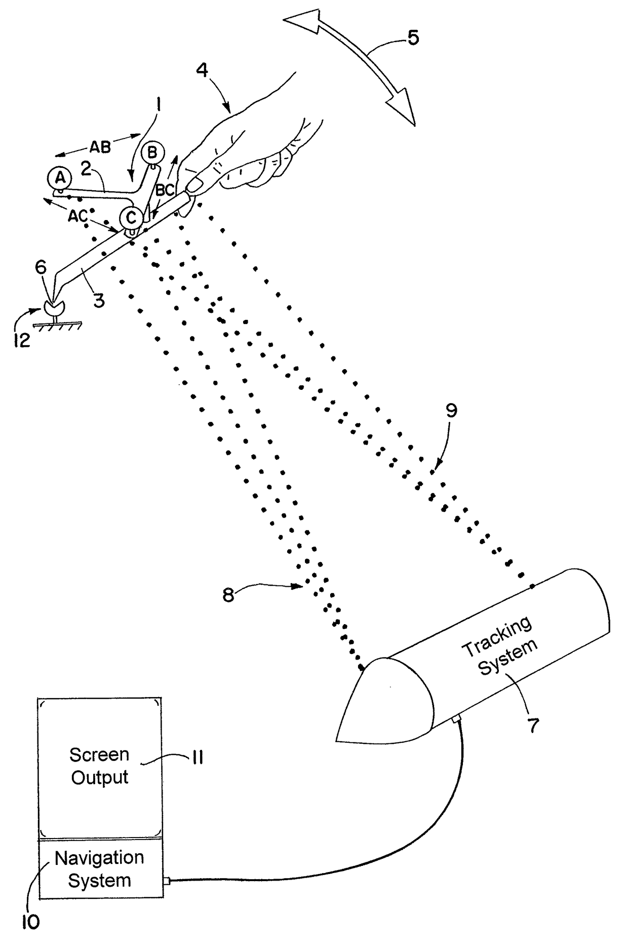
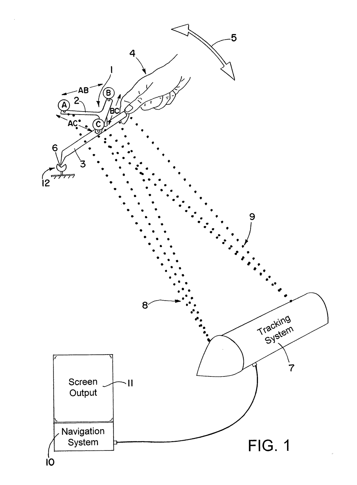
[0024]FIG. 1 illustrates an exemplary rigid body that includes marker elements, wherein the rigid body is identified by means of a navigation and / or tracking system. More specifically, the marker elements A, B, and C may be arranged on a reference array 1 via arms 2 and attached to an instrument 3, wherein the rigid body may be identified by moving the instrument 3 within the working range of the navigation system 10 and / or tracking system 7. While an optical tracking is shown, other tracking systems may be utilized, including, for example, ultrasound, magnetic or laser tracking and navigation systems.

[0025]The instrument 3 comprises a tip 6, and a spatial arrangement of the marker elements A, B, and C on the reference array 1 is fixed, such that the distances AB, AC and BC of the three marker elements form a rigid body and / or rigid marker body geometry. The distances AB, AC and BC can be detected by the tracking system 7, which can operate stereoscopically, i.e., using two cameras ...


PUM


Abstract

A method for using a medical navigation system to identify an instrument to be navigated is provided, wherein the instrument includes a reference array having a plurality of markers that form a rigid body, and a location of the markers with respect to each other is not previously known in the navigation system as a characteristic arrangement for a particular instrument. The method includes measuring a distance of each marker relative to the other markers; identifying a spatial arrangement of the markers having the measured distance as an assignable marker array; assigning the assignable marker array to the instrument; and identifying the instrument based on the assigned marker array.

Description

RELATED APPLICATION DATA[0001]This application claims priority of U.S. Provisional Application No. 60 / 806,508 filed on Jul. 3, 2006, which is incorporated herein by reference in its entirety.FIELD OF THE INVENTION[0002]The invention relates to a method and system for identifying an instrument, such as a navigated medical instrument.BACKGROUND OF THE INVENTION[0003]Medical navigation systems are known and used to provide operating physicians with visual assistance during operations. Such visual assistance may include indicating a location of positionally determined and tracked instruments with respect to particular parts of the patient's body. The information concerning the body parts can be previously or intra-operatively ascertained using imaging methods. Further, with the aid of an initial registration procedure, the spatial positions of the patient, the corresponding image data and the instruments used in the operating theater can be assigned such that navigation and / or image-ass...

Claims


Application Information

Patent Timeline
Patent Type & Authority Patents(United States)
IPC IPC(8): A61B34/20A61B17/00A61B90/00
CPCA61B90/39A61B34/20A61B2017/00725A61B2034/2055A61B2090/3983
Inventor GOLDBACH, GUNTER
Owner BRAINLAB
Why Eureka
Try Eureka