Gear machining device and gear machining method

a gear machining and gear technology, applied in the direction of gear teeth, gear-teeth manufacturing apparatus, lapping machines, etc., can solve the problems of increasing cutting resistance, generating self-induced vibration, worsening the accuracy of tooth trace, etc., to achieve high precision gears, maintain accuracy of machining, and improve the life of machining tools

Active Publication Date: 2017-04-18
JTEKT CORP
View PDF19 Cites 2 Cited by
  • Summary
  • Abstract
  • Description
  • Claims
  • Application Information

AI Technical Summary

Benefits of technology

[0011]According to the above structure, since the tooth bottoms, the first side surfaces and the second side surfaces of teeth of a gear can be machined separately in sequence, the respective blade of the machining tool is used for cutting only a portion of the tooth. This can reduce the cutting resistance and accordingly, the generation of the self-induced vibrations, to thereby improve the tooth trace accuracy (reduction of waviness of the tooth trace) of a gear.
[0013]According to the structure of the second aspect of the invention, the optimum tool states of the machining tool before and after the grinding thereof can be obtained. Therefore, even the number of grinding time is increased, the accuracy of machining can be maintained and the duration of life of the machining tool can be improved. At the same time, a highly precise gear with low in cost can be produced.
[0015]According to the above method, since the tooth bottoms, the first side surfaces and the second side surfaces of the teeth of the gear can be machined separately in sequence, the blades of the machining tool are used for cutting only a portion of the tooth. This can reduce the cutting resistance and accordingly, the generation of the self-induced vibrations to thereby improve the tooth trace accuracy (reduction of waviness of the tooth trace) of the gear.
[0017]According to the method of another aspect of the invention, the optimum tool states of the machining tool before and after the grinding can be obtained. Therefore, even the number of grinding time is increased, the accuracy of machining can be maintained and the duration of life of the machining tool can be improved. At the same time, a highly precise gear with low in cost can be produced.

Problems solved by technology

However, according to the conventional machining device, since the plurality of cutting blade portions contacts with the workpiece at the same time, the cutting resistance tends to be increasing which may generate self-induced vibrations upon cutting operation.
This may worsen the tooth trace accuracy (generation of waviness of the tooth trace).
However, in such case, the rigidity of the machining tool may be deteriorated.

Method used


Image

  • Gear machining device and gear machining method
  • Gear machining device and gear machining method
  • Gear machining device and gear machining method

Examples


Embodiment Construction

[0047](Mechanical Structure of Gear Machining Device)

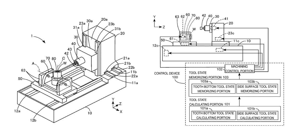
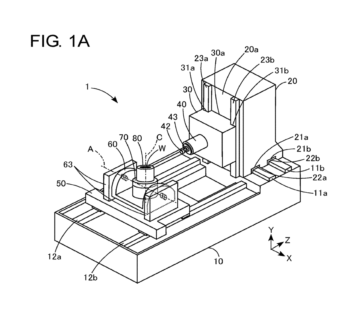
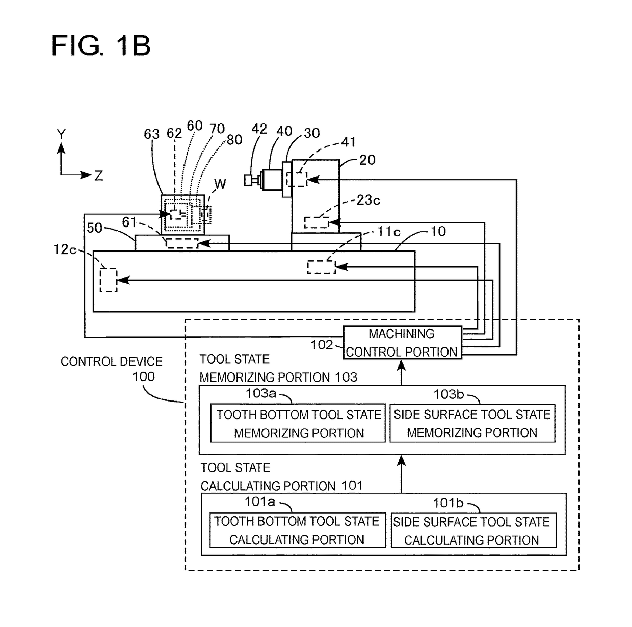
[0048]According to this embodiment, as an example of a gear machining device 1, a five-axis machining center is exampled and will be explained with reference to FIGS. 1A and 1B. In other words, the gear machining device 1 includes mutually intersecting three linear axes (X, Y and Z axes) and two rotary axes (A and C axes) as the drive axes.

[0049]As shown in FIGS. 1A and 1B, the gear machining device 1 includes a bed 10, a column 20, a saddle 30, a rotary main spindle 40, a table 50, a tilt table 60, a turn table 70, a workpiece holder 80 and a control device 100, and so on. It is noted that although it is not shown in the drawings, but normally a known automatic machining tool exchange device is arranged alongside the bed 10.

[0050]The bed 10 is of approximately a rectangular shape and arranged on the floor. It is noted that the shape of the bed is not limited to the rectangular shape and any shape would be used therefor. A pair of...


PUM

PropertyMeasurementUnit
intersecting angleaaaaaaaaaa
inclination angleaaaaaaaaaa
angleaaaaaaaaaa

Abstract

A gear machining device for machining a gear by using a machining tool which has a rotation axis inclined relative to a rotation axis of a workpiece and feeding the machining tool relatively in the rotation axis direction of the workpiece by rotating the machining tool in synchronization with a rotation of the workpiece. The gear machining device includes a tool state memorizing portion for memorizing a tool state including a position or a posture of the machining tool relative to the workpiece for machining a tooth bottom, first and second side surfaces of the gear and a machining control portion for controlling machining of the workpiece under each tool state of the machining tool memorized in the tool state memorizing portion.

Description

INCORPORATION BY REFERENCE[0001]This application is based on and claims priority under 35 U.S.C. 119 with respect to Japanese Applications No. 2014-226843 and No. 2014-226844 both filed on Nov. 7, 2014, and Japanese Applications No. 2015-205565 and No. 2015-205566 both fled on Oct. 19, 2015, the entire content of which is incorporated herein by reference.BACKGROUND OF THE INVENTION[0002]Field of the Invention[0003]This invention relates to a gear machining device and a gear machining method for machining a gear by cutting machining by synchronizing a rotation of a machining tool with a rotation of a workpiece to be machined.[0004]Description of Related Arts[0005]As an effective measure for machining both internal and external teeth by cutting machining, a machining device disclosed in a Patent Document 1 (JPH01-159126 A) may be exampled. The machining device according to this conventional technology produces gear teeth by cutting with synchronized rotations of a workpiece and a mach...

Claims


Application Information

Patent Timeline
Patent Type & Authority Patents(United States)
IPC IPC(8): B23F23/08B24B37/013B23F1/06
CPCB23F1/06B23F23/085
Inventor OTANI, HISASHITAKESHITA, KICHIJINAKANO, HIROYUKIZHANG, LIN
Owner JTEKT CORP
Why Eureka
Try Eureka