Methods for NOx reduction using exhaust-gas condensate

a technology of exhaust gas and condensate, which is applied in the direction of non-fuel substance addition to fuel, machines/engines, mechanical equipment, etc., can solve the problems of nox emissions, water carried onboard in this way can freeze at low ambient temperature, scarce use of water in motor vehicles, etc., to reduce nox emissions, reduce combustion temperature within the engine, the effect of reducing nox emissions

Active Publication Date: 2017-05-09
FORD GLOBAL TECH LLC
View PDF7 Cites 3 Cited by
  • Summary
  • Abstract
  • Description
  • Claims
  • Application Information

AI Technical Summary

Benefits of technology

[0005]In one example, a system and methods is based upon the insight that the engine exhaust gas comprises a high fraction of water vapor. In this way, the technical result is achieved that the high fraction of water vapor within the exhaust gas may be further used for the reduction of NOx emissions by injecting the condensed water into the combustion air of the engine in order to lower a combustion temperature within the engine. As such, systems and methods are conceived of wherein the NOx emissions may be reduced without using a user-refillable water tank, which thereby reduces space requirements on-board a vehicle, and also reduces a vehicle weight and operating complexities for the driver. Furthermore, a method according to the present disclosure eliminates problems with regard to the freezing of the water store carried onboard the vehicle.

Problems solved by technology

However, this approach is scarcely used in motor vehicles and has been realized only occasionally in heavy goods vehicles.
In particular, in the case of passenger motor vehicles, the reduction in the emissions of NOx through the admixing of water into the combustion air is not presently used because such measures are often associated with considerable additional outlay for the storage of water, which has a disadvantage in that the water must be replenished at regular intervals.
Moreover, disadvantages arise in that the water carried onboard in this way can freeze at low ambient temperatures.

Method used


Image

  • Methods for NOx reduction using exhaust-gas condensate
  • Methods for NOx reduction using exhaust-gas condensate
  • Methods for NOx reduction using exhaust-gas condensate

Examples


Embodiment Construction

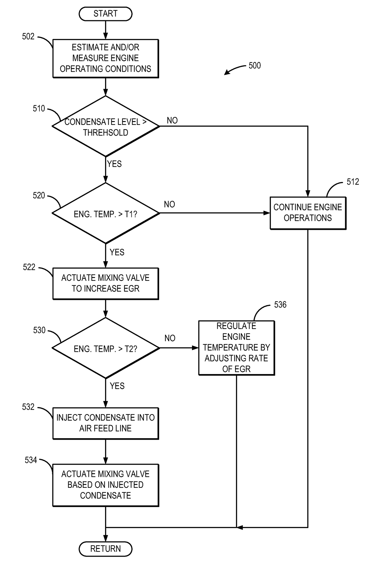
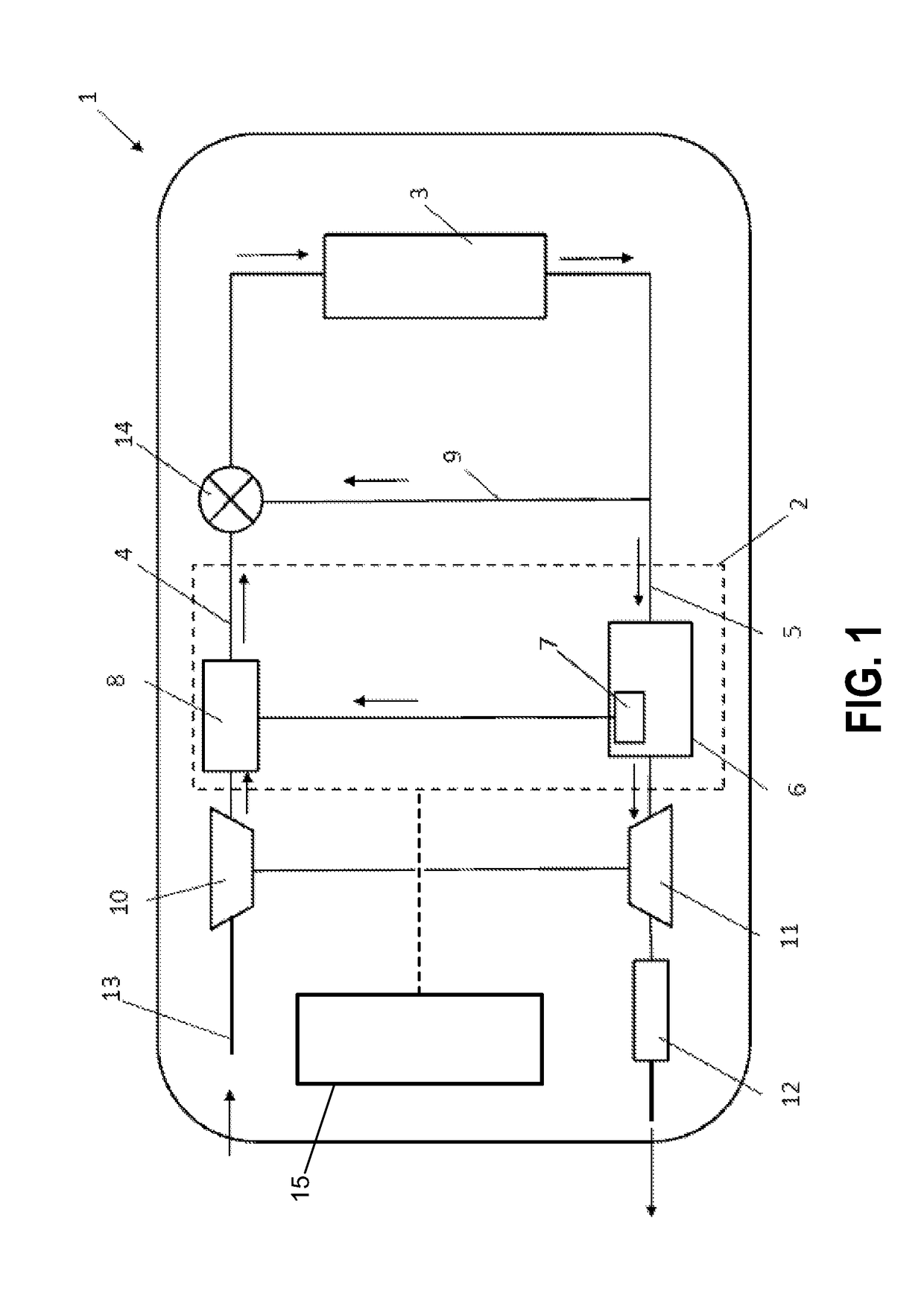
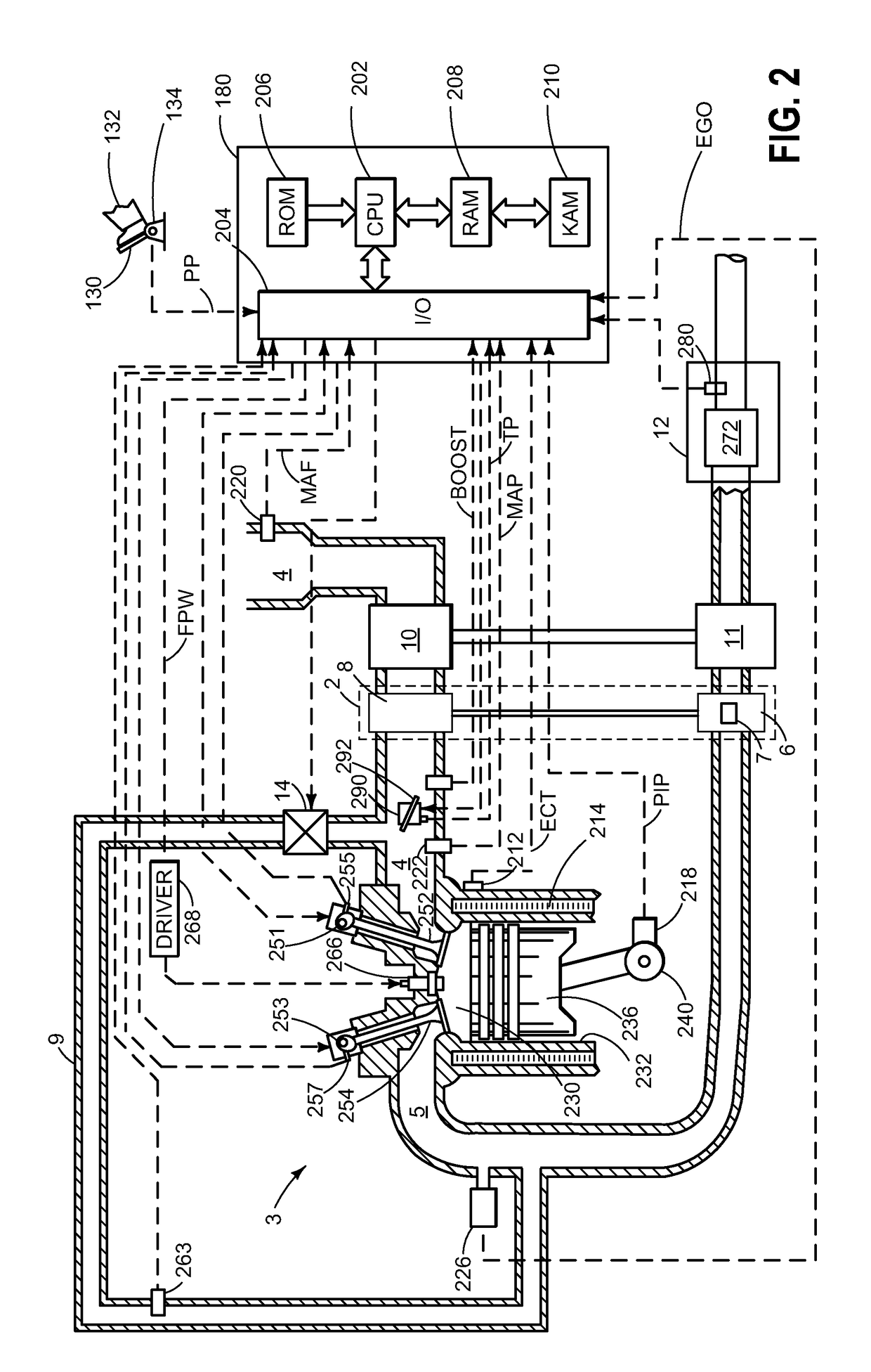
[0016]An engine comprising a recirculation device according to the present disclosure allows the exhaust line to be coupled to the air feed line via a cooling unit for collecting condensate on board the vehicle during operation. In this way, the recirculation device described may collect condensate from the exhaust-gas stream and further conduct the collected condensate to the air feed line for injection into the combustion air to cool the engine and thereby reduce NOx emissions therefrom. For this reason, exemplary vehicle diagrams are shown in FIGS. 1 and 2 to illustrate one possible configuration of the disclosed recirculation device. Example flow charts shown in FIGS. 3-8 further illustrate various methods for using the disclosed recirculation device to adjust an amount of water vapor formed and used within the example engine system.

[0017]Turning to a description of the system, FIG. 1 shows a block diagram of a motor vehicle according to the present disclosure. As shown, motor v...


PUM


Abstract

The system and methods described allow for reduce emissions by using a recirculation device within an engine that connects an air feed line to an exhaust line while cooling the exhaust-gas to form a condensate for further cooling the engine system. In one particular example, a cooling unit is described that cools the exhaust-gas stream flowing there through and collects a condensate out of the exhaust-gas stream for injection back into the air feed line via an injecting device. In this way, an injection of water may be made to reduce NOx emissions during vehicle operations, and the outlay for storage of water on board the vehicle may be eliminated.

Description

CROSS REFERENCE TO RELATED APPLICATIONS[0001]The present application claims priority to German Patent Application No. 102013200185.1, filed on Jan. 9, 2013, the entire contents of which are hereby incorporated by reference for all purposes.FIELD[0002]The present description relates to a recirculation device for an internal combustion engine, to a combustion apparatus having a recirculation device of said type, to a motor vehicle having a combustion apparatus of said type, and to a method for operating a combustion apparatus.BACKGROUND AND SUMMARY[0003]Owing to ever-increasing demands on the purity of exhaust-gas released from motor vehicles, methods are sought to reduce the formation of emissions during the combustion of fuel within the engine, and to chemically or physically convert emissions formed into more inert substances. In particular, a reduction in the emissions of nitrogen oxides, commonly referred to as NOx for short, is sought. In the case of large engines such as diesel...

Claims


Application Information

Patent Timeline
Patent Type & Authority Patents(United States)
IPC IPC(8): F01N3/00F02M25/028F02M25/022
CPCF02M26/29F01N3/005F02M25/028F02M25/0222Y02T10/121Y02T10/20Y02T10/12
Inventor RUHLAND, HELMUT HANSWILLEMS, WERNERHERUDEK, CLAUDIA KATHARINACONEE, CLAUDIACHEN, GUOHUI
Owner FORD GLOBAL TECH LLC
Why Eureka
Try Eureka