Arc detection and prevention in a power generation system

a power generation system and arc detection technology, applied in power supply testing, fault location by conductor type, instruments, etc., can solve problems such as fire, arcing may occur in relay contacts, circuit breakers, fuses and poor cable terminations, etc., to reduce the overall cost, prolong the useful life of such systems, and achieve the effect of photovoltaic system deploymen

Active Publication Date: 2017-05-09
SOLAREDGE TECH LTD
View PDF1413 Cites 64 Cited by
  • Summary
  • Abstract
  • Description
  • Claims
  • Application Information

AI Technical Summary

Benefits of technology

[0007]As newly described herein, systems and methods are presented to address the problem of arching in photovoltaic systems, thereby reducing the overall cost, and extending the useful lifespan of such systems. The embodiments described herein, therefore, make deployment of photovoltaic systems in residential and industrial application more competitive with nonrenewable energy alternatives.

Problems solved by technology

Arcing may occur in switches, circuit breakers, relay contacts, fuses and poor cable terminations.
If a circuit has enough current and voltage to sustain an arc, the arc can cause damage to equipment such as melting of conductors, destruction of insulation, and fire.
A direct current system may be more prone to arcing than AC systems because of the absence of zero crossing in DC power systems.
Electric arcing can have detrimental effects on electric power distribution systems and electronic equipment, and in particular, photovoltaic systems, which are often arranged in a manner that increases the risk of arching.
For example, photovoltaic panels often operate at extreme temperatures due to their necessary exposure to the sun.
Such conditions cause accelerated deterioration in insulation and other equipment that can lead to exposed wires.
Such systems are also exposed to environmental conditions, such as rain, snow, and high humidity.
This problem of arching raises system maintenance cost and reduces the lifespan of photovoltaic panels, because photovoltaic panels and other related equipment will need to be repaired and / or replaced more frequently.
Arching in photovoltaic systems also increases the risk of fire, thereby increasing operating and / or insurance cost on facilities having photovoltaic systems.

Method used


Image

  • Arc detection and prevention in a power generation system
  • Arc detection and prevention in a power generation system
  • Arc detection and prevention in a power generation system

Examples


Embodiment Construction

[0026]Reference will now be made in detail to embodiments, examples of which are illustrated in the accompanying drawings, wherein like reference numerals refer to the like elements throughout. The embodiments are described below to explain the present invention by referring to the figures.

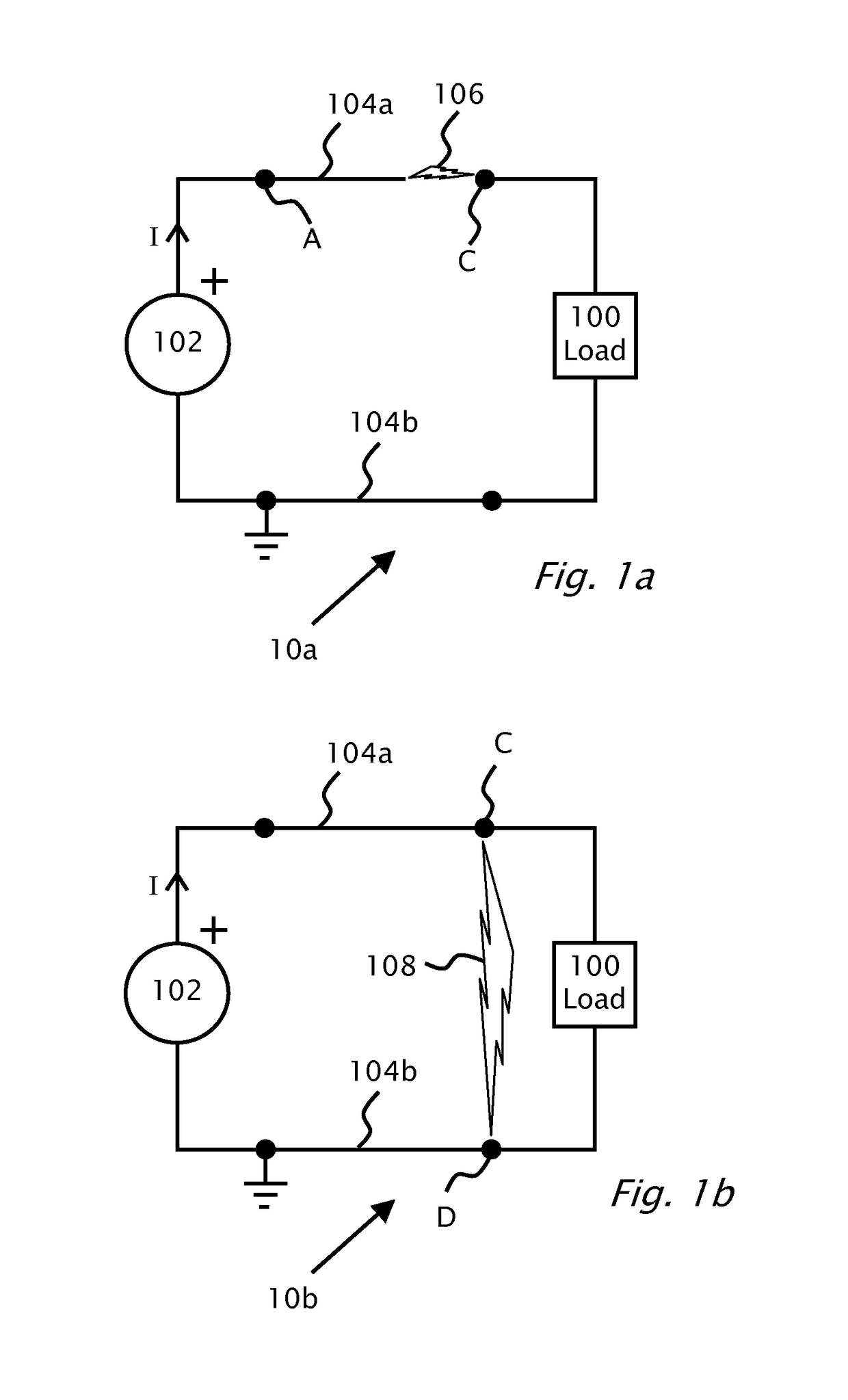
[0027]Reference is made to FIG. 1a which shows serial arcing 106 in a circuit 10a according to background art. In FIG. 1a, a direct current (DC) power supply 102 provides power between power lines 104a and 104b. Power line 104b is shown at ground potential. Load 100 connects power line 104b to power line 104a. Serial arcing may occur in any part of circuit 10a in power lines 104a, 104b or internally in load 100 or supply 102 for example. A disconnection or poor connection in power line 104a between point C and point A is shown which causes an instance 106 of serial arcing. Typically, if series arc 106 can be detected, circuit breakers (not shown) located at supply 102 or load 100 can be tripped to...


PUM


Abstract

A method for arc detection in a system including a photovoltaic panel and a load connectible to the photovoltaic panel with a DC power line. The method measures power delivered to the load thereby producing a first measurement result of the power delivered to the load. Power produced by the photovoltaic panel is also measured, thereby producing a second measurement result of power produced by the photovoltaic panel. The first measurement result is compared with the second measurement result thereby producing a differential power measurement result. Upon the differential power measurement result being more than a threshold value, an alarm condition may also be set. The second measurement result may be modulated and transmitted over the DC power line.

Description

CROSS REFERENCE TO RELATED APPLICATIONS[0001]The present application claims priority to patent application GB1018872.0, filed Nov. 9, 2010, in the United Kingdom Intellectual Property Office. Application GB1018872.0 is incorporated by reference in its entirety.FIELD[0002]The present invention is related to distributed power generation systems and specifically to arc detection and prevention in photovoltaic power generation systems.BACKGROUND[0003]A distributed photovoltaic power generation system may be variously configured, for example, to incorporate one or more photovoltaic panels mounted in a manner to receive sunlight such as on a roof of a building. An inverter may be connected to the photovoltaic panels. The inverter typically converts the direct current (DC) power from the photovoltaic panels to alternating current (AC) power.[0004]Arcing may occur in switches, circuit breakers, relay contacts, fuses and poor cable terminations. When a circuit is switched off or a bad connec...

Claims


Application Information

Patent Timeline
Patent Type & Authority Patents(United States)
IPC IPC(8): H02H7/122H02H1/00H02J1/00H01L31/02H02H7/20G01R31/12
CPCH02H1/0015H01L31/02021H02H7/20G01R31/1227Y02E10/50H02S50/10G01R31/12H02S50/00G01R31/086G01R31/40H02H3/087H02H7/1222Y02E10/56
Inventor YOSCOVICH, ILANSELLA, GUYGAZIT, MEIRGALIN, YOAVBRAGINSKY, DAVIDHANDELSMAN, LIORADEST, MEIR
Owner SOLAREDGE TECH LTD
Why Eureka
Try Eureka