Illumination device and temperature calibration method

a technology of temperature calibration and illumination device, which is applied in the direction of lamp testing, electroluminescent light source, electric lighting source, etc., can solve the problems of binning alone not being able to compensate for the change in led output characteristics output characteristics that tend to vary over temperature, process and time, etc., to achieve the effect of reducing costs and simplifying the calibration process

Active Publication Date: 2017-05-16
LUTRON TECH CO LLC
View PDF286 Cites 44 Cited by
  • Summary
  • Abstract
  • Description
  • Claims
  • Application Information

AI Technical Summary

Benefits of technology

[0028]In some embodiments, the illumination device may be subjected to the first and second ambient temperatures by artificially generating the temperatures during the calibration process. However, it is generally preferre...

Problems solved by technology

Although LEDs have many advantages over conventional light sources, a disadvantage of LEDs is that their output characteristics tend to vary over temperature, process and time.
However, the luminous flux generated by an LED for a given drive current does not remain constant over temperature and time, and gradually decreases with increasing temperature and as the LED ages over time.
However, binning alone cannot compensate for changes in LED output characteristics due to aging and temperature fluctuations during use of the LED device.
While heat sinks are generally needed for thermal dissipation, adding temperature sensors to the chip unnecessarily increases the cost of the LED device and consumes valuable chip real estate.
More importantly, the temperature sensors and heat sinks added to the chip often cannot provide an accurate temperature measurement for all LEDs included with the LED device.
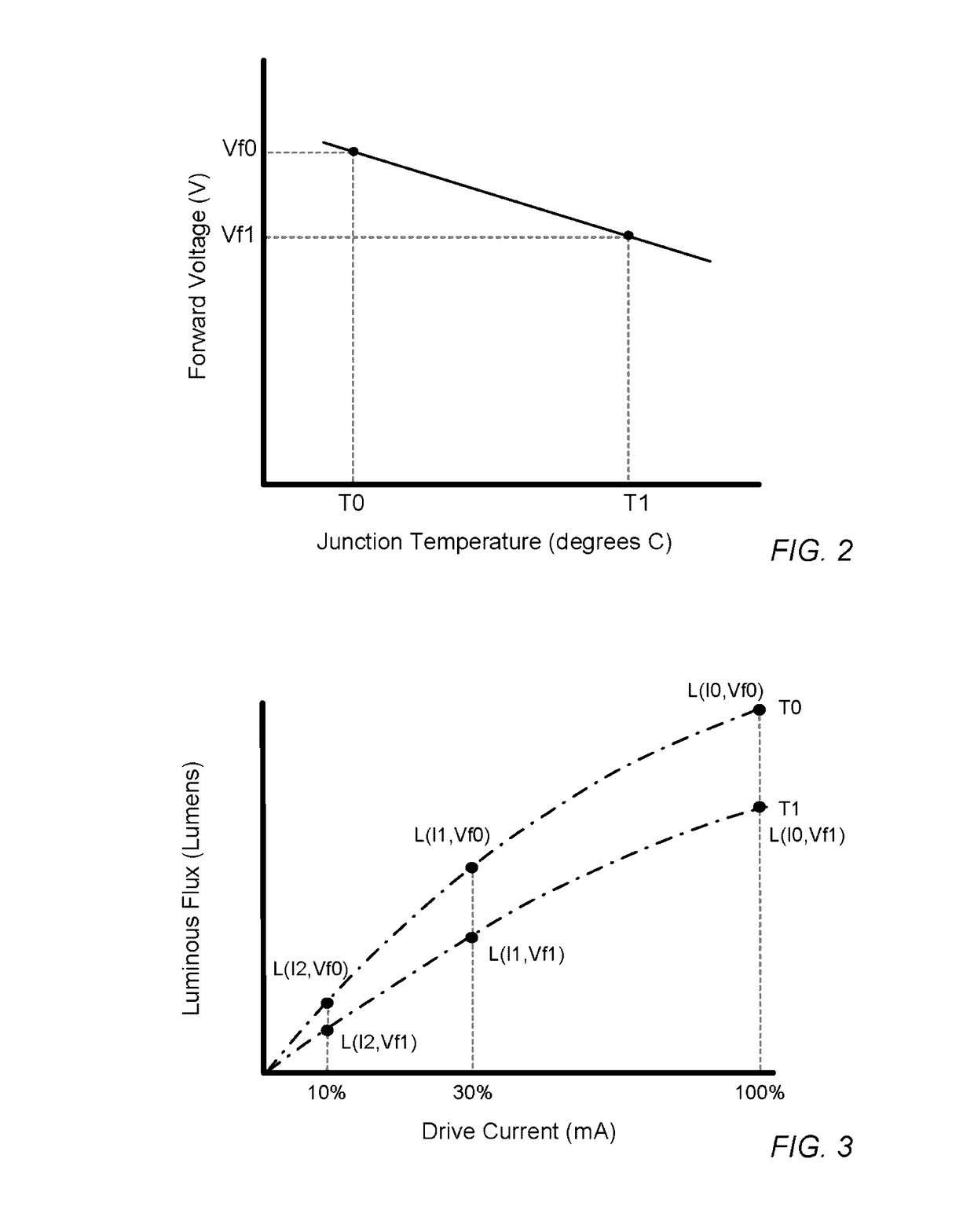
However, most manufacturers of conventional LED devices fail to account for the fact that the magnitude and slope of the line correlating forward voltage to junction temperature (shown, e.g., in FIG. 14) can vary significantly between LED manufacturers, LED part numbers and even individual LEDs arranged side by side on the same chip.
While the differences in slope are typically small, they can represent a few degrees C. measurement error over the operating temperature range of an LED.
These measurement errors result in inaccurate temperature compensation if steps are not taken to account for these variations when calibrating conventional LED devices.
In addition to variations in forward voltage, most manufacturers fail to account for the non-linear relationship between luminous flux and junction temperature for certain colors of LEDs, and the non-linear relationship between luminous flux and drive current for all colors of LEDs.
Without accounting for such non...

Method used


Image

  • Illumination device and temperature calibration method
  • Illumination device and temperature calibration method
  • Illumination device and temperature calibration method

Examples


Embodiment Construction

[0054]An LED generally comprises a chip of semiconducting material doped with impurities to create a p-n junction. As in other diodes, current flows easily from the p-side, or anode, to the n-side, or cathode, but not in the reverse direction. Charge-carriers—electrons and holes—flow into the junction from electrodes with different voltages. When an electron meets a hole, it falls into a lower energy level, and releases energy in the form of a photon (i.e., light). The wavelength of the light emitted by the LED, and thus its color, depends on the band gap energy of the materials forming the p-n junction of the LED. Red and yellow LEDs are commonly composed of materials (e.g., AlInGaP) having a relatively low band gap energy, and thus produce longer wavelengths of light. For example, most red and yellow LEDs have a peak wavelength in the range of approximately 610-650 nm and approximately 580-600 nm, respectively. On the other hand, green and blue LEDs are commonly composed of materi...


PUM


Abstract

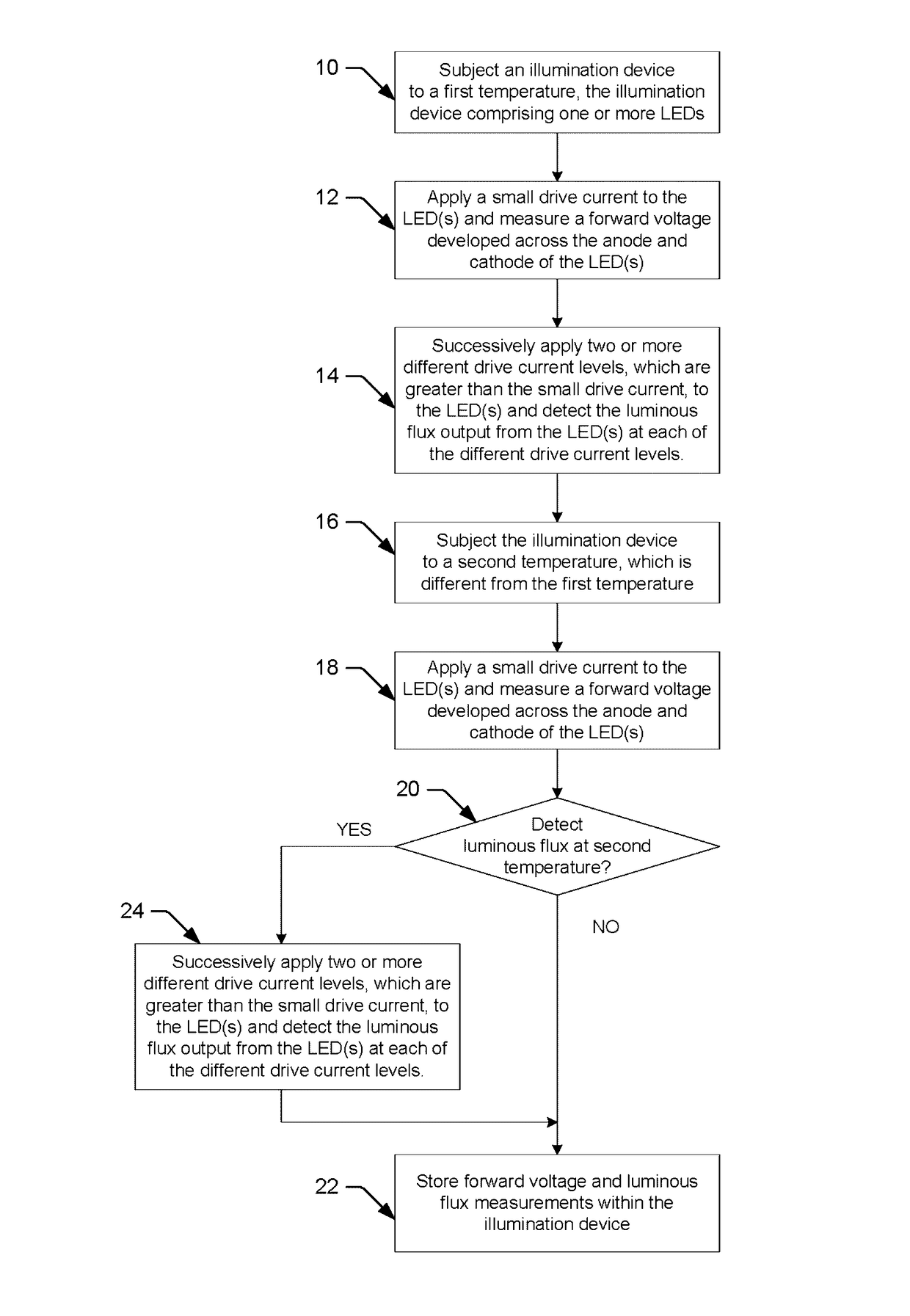
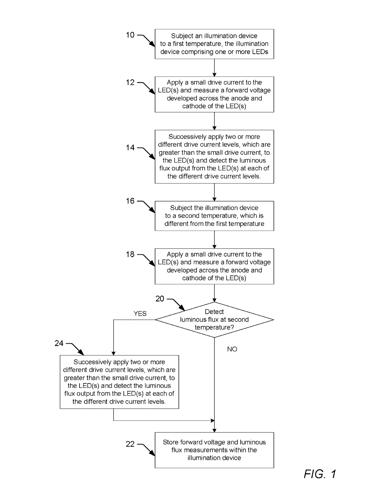
An illumination device comprising a plurality of light emitting diodes (LEDs) and a method for calibrating the illumination device is provided herein. According to one embodiment, the method may include subjecting a first LED to a first ambient temperature, measuring a forward voltage developed across the first LED upon applying a relatively small drive current to the first LED, detecting at least a first, a second and a third luminous flux output from the first LED upon successively applying at least a first, a second and a third drive current to the first LED, and storing results of the measuring and detecting steps within the illumination device to calibrate the first LED at the first ambient temperature. In some embodiments, the first LED may be subjected to a second ambient temperature, which is different from the first ambient temperature, and the method may repeat the steps of measuring, detecting and storing to calibrate the first LED at the second ambient temperature.

Description

BACKGROUND OF THE INVENTION[0001]1. Field of the Invention[0002]This invention relates to illumination devices and, more particularly, to illumination devices comprising a plurality of light emitting diodes (LEDs) and to methods for calibrating and compensating individual LEDs in an illumination device, so as to maintain a desired luminous flux and / or a desired color point of the device over variations in temperature and process while avoiding undesirable visual artifacts, such as brightness banding and flicker.[0003]2. Description of the Relevant Art[0004]The following descriptions and examples are provided as background only and are intended to reveal information that is believed to be of possible relevance to the present invention. No admission is necessarily intended, or should be construed, that any of the following information constitutes prior art impacting the patentable character of the subjected mater claimed herein.[0005]Lamps and displays using LEDs (light emitting diode...

Claims


Application Information

Patent Timeline
IPC IPC(8): H05B33/08H05B37/02G01R31/44H05B44/00
CPCG01R31/44H05B33/0869H05B33/0854H05B33/0848H05B33/0866H05B45/24H05B45/18H05B45/10H05B45/22H05B45/14
Inventor KNAPP, DAVID J.HO, HORACE C.SAVAGE, JOSEPH A.
Owner LUTRON TECH CO LLC
Why Eureka
Try Eureka