Method and apparatus for storing information using an intelligent block storage controller

a technology of intelligent block storage and storage controller, which is applied in the direction of redundant data error correction, fault response, instruments, etc., can solve the problems of reducing the number of lifetime program/erase cycles, reducing the feature size, and creating many challenges, so as to reduce warranty costs, reduce failure rates, and increase the lifetime of storage drives

Active Publication Date: 2017-05-30
DIVERGENT STORAGE SYST INC
View PDF14 Cites 18 Cited by
  • Summary
  • Abstract
  • Description
  • Claims
  • Application Information

AI Technical Summary

Benefits of technology

[0022]On the other hand, the disclosed technologies maintain data storage operations in the level of physical blocks. When a physical block is damaged, the whole physical storage drive does not become useless. Rather, the disclosed technologies adopt another available physical block to repair the damaged physical block. Advantages of the technologies include reducing failure rates and reducing warranty costs. The disclosed technologies further benefit IT operators by increasing the lifetime of storage drives, reducing operational expenditure, lowering overhead for rebuilds, and minimizing data privacy concerns. In addition, the technologies ease the management of storage drives.
[0023]In one aspect, disclosed herein is a method for improving data storage reliability and efficiency, the method comprising: (a) creating at least one logical storage drive comprising a plurality of logical blocks; (b) mapping the at least one logical storage drive to at least one physical storage drive based on many-to-one mapping or one-to-many mapping, wherein the at least one physical storage drive comprises a plurality of physical blocks; and (c) applying a compression algorithm to data held in one or more logical blocks, aggregating units of the data, and storing the units of the data into one or more physical blocks. In some embodiments, the method further comprises connecting to the at least one physical storage drive based on one or more of the following: a small computing system interface (SCSI), a serial attached SCSI (SAS), a serial at attachment (SATA), an Internet SCSI (iSCSI), a fiber channel, an InfiniBand, a peripheral component interconnect (PCI), and a peripheral component interconnect express (PCIe). In some embodiments, the at least one physical storage drive comprises one or more of the following: a hard drive, a solid-state drive, an optical drive, and a tape drive. In some embodiments, a number of the plurality of logical blocks is larger than a number of physical blocks used to map the plurality of logical blocks. In some embodiments, the mapping comprises mapping at least two logical blocks to a physical block. In some embodiments, the mapping comprises mapping at least two physical blocks to a logical block. In some embodiments, the method further comprises transforming access to the at least one logical storage drive into a process of accessing to the at least one physical storage drive. In some embodiments, the method further comprises assigning the at least one logical storage drive with a logical unit number. In some embodiments, the method further comprises associating a logical block with a logical block address. In some embodiments, the method further comprises receiving a request from a computing system to write the data, wherein the computing system provides an associated logical block address of the data. In additional embodiments, the method further comprises responding to the request to write the data. In additional embodiments, the method further comprises copying the data from the one or more logical blocks to one or more non-transitory media and tracking an associated logical block address. In additional embodiments, the one or more non-transitory media preserve the data during the data write when power outage happens. In some embodiments, the one or more non-transitory media comprise one or more of: a non-volatile memory, a solid state drive, torque spin transfer memory, phase change memory, resistive RAM, and the at least one physical storage drive. In additional embodiments, the data is in a compressed form when the data is compressible, or is in an original form when the data is incompressible, or is in the original form when the applying the compression algorithm is performed after the copying the data. In some embodiments, the method further comprises deleting the data from the one or more non-transitory media upon the data is stored in the one or more physical blocks. In some embodiments, the method further comprises acknowledging completion of writing the data to the computing system. In some embodiments, the acknowledging is not made until the data held in the one or more logical blocks is completely written into the one or more non-transitory media. In some embodiments, the acknowledging is not made until the data held in the one or more logical blocks is completely written into the one or more physical blocks. In some embodiments, the method further comprises receiving a request from a computing system to read requested data, wherein the computing system provides an associated logical block address of the requested data. In some embodiments, the method further comprises determining if the requested data is in one or more non-transitory media. In some embodiments, the one or more non-transitory media comprise one or more of: a non-volatile memory, a solid state drive, torque spin transfer memory, phase change memory, resistive RAM, and the at least one physical storage drive. In some embodiments, the method further comprises, when the requested data is in the one or more non-transitory media, returning the requested data to the computing system from the one or more non-transitory media. In some embodiments, the method further comprises, when the requested data is not in the one or more non-transitory media, determining if the requested data is in a compressed form in the at least one physical storage drive. In some embodiments, the method further comprises, when the requested data is in the compressed form, reading the requested data from the one or more physical blocks, decompressing the requested data and returning the requested data to the computing system. In some embodiments, the method further comprises, when the requested data is not in the compressed form, reading the requested data from the one or more physical blocks and returning the requested data to the computing system. In some embodiments, the method further comprises claiming a free storage space by analyzing the plurality of physical blocks and the plurality of logical blocks. In some embodiments, the analyzing comprises evaluating statistics of occupied physical blocks and vacant physical blocks. In some embodiments, the analyzing comprises evaluating a percentage of valid logical blocks and re-written logical blocks mapped into the one or more physical blocks. In some embodiments, the analyzing comprises comparing valid logical blocks and invalid logical blocks on a physical-block-by-physical-block basis to identify one or more candidate physical blocks for the claiming the free storage space. In some embodiments, the claiming the free storage space comprises combining a first set of logical blocks from a first set of physical blocks and a second set of logical blocks from a second set of physical blocks into a third set of physical blocks without transferring stored data into and out of the at least one physical storage drive. In some embodiments, the at least one logical storage drive comprises at least one protected logical storage drive. In some embodiments, the method further comprises receiving a request from a computing system to write the data to the at least one protected logical storage drive, wherein the computing system provides associated logical block addresses of one or more logical blocks of the data. In some embodiments, the method further comprises concatenating the one or more logical blocks to form a data unit. In some embodiments, the method further comprises segmenting the data unit into data sub-units. In some embodiments, the method further comprises performing error-correction coding on the data sub-units. In some embodiments, the applying the compression algorithm, the aggregating, and the segmenting are performed in an arbitrary order. In some embodiments, the method further comprises generating redundancy sub-units from the data sub-units. In some embodiments, the method further comprises writing the data sub-units and the redundancy sub-units into the at least one physical storage drive. In some embodiments, the method further comprises receiving a request from a computing system to read requested data from the at least one protected logical storage drive, wherein the computing system provides associated logical block addresses of one or more logical blocks of the requested data. In some embodiments, the method further comprises reading data sub-units of the requested data from the at least one physical storage drive. In some embodiments, the method further comprises reading redundancy sub-units of the requested data from the at least one physical storage drive. In some embodiments, the method further comprises generating missing data sub-units of the requested data using the redundancy sub-units. In some embodiments, the method further comprises concatenating the data sub-units to form a data unit. In some embodiments, the method further comprises determining if the data unit is in a compressed form. In some embodiments, the method further comprises, when the data unit is in the compressed form, traversing headers of the data unit to identify logical block addresses. In some embodiments, the method further comprises, when the data unit is in the compressed form, decompressing the data unit and returning the requested data to the computing system. In some embodiments, the method further comprises, when the data unit is not in the compressed form, returning the requested data to the computing system. In some embodiments, the method further comprises protecting the data by encrypting the data. In some embodiments, the method further comprises encrypting the data by an encryption key. In some embodiments, the method further comprises creating a spare and unused storage capacity through the compression algorithm in the at least one physical storage drive. In some embodiments, the method further comprises using the spare and unused storage capacity to remap a failed physical block of the at least one physical storage drive, the failed physical block occurring without warning. In some embodiments, the method further comprises failing a first logical drive mapped into the failed physical block to a computing system. In some embodiments, the method further comprises creating a new mapping for a second logical drive, wherein (a) the second logical drive replaces the first logical drive and (b) the new mapping excludes the failed physical block and replaces the failed physical block with a second physical block. In some embodiments, the second physical block is located in the spare and unused storage capacity. In some embodiments, the method further comprises presenting the second logical drive to a computing system. In some embodiments, the method further comprises using the spare and unused storage capacity to remap a predicted-to-be-failed physical block of the at least one physical storage drive, the predicted-to-be-failed physical block occurring with a warning of a future failure. In some embodiments, the method further comprises receiving a notification of the future failure. In some embodiments, the method further comprises mapping a set of logical blocks associated with the predicted-to-be-failed physical block to a second physical block, wherein the second physical block is in the spare and unused storage capacity. In some embodiments, the method further comprises migrating data from the predicted-to-be-failed physical block into the second physical block. In some embodiments, the method further comprises, upon completion of the migrating, dissociating the predicted-to-be-failed physical block from the set of logical blocks. In some embodiments, the method further comprises using the spare and unused storage capacity to expand a logical capacity of the at least one logical storage drive. In some embodiments, the logical capacity viewed by a computing system is larger than a physical capacity of associated physical blocks. In some embodiments, the logical capacity is derived by past entropy or expected future entropy of writes to the at least one logical storage drive. In some embodiments, the method further comprises using the spare and unused storage capacity to store redundancy information. In some embodiments, the method further comprises creating redundancy information for new data write without a need to read back previous writes. In some embodiments, the applying the compression algorithm and the aggregating the units of the data are performed in an arbitrary order. In some embodiments, the method is implemented based on one or more of the following: a peripheral component interconnect (PCI) card, a peripheral component interconnect express (PCIe) card, field programmable gate arrays (FPGA), application specific integrated circuit (ASIC), and computing cycles of a processor.
[0024]In another aspect, disclosed herein is a method for improving data storage reliability and efficiency, the method comprising: (a) creating at least one logical storage drive comprising a plurality of logical blocks; (b) mapping the at least one logical storage drive into at least one physical storage drive based on many-to-one mapping or one-to-many mapping, wherein the at least one physical storage drive comprises a plurality of physical blocks; and (c) applying a compression algorithm to data held in one or more logical blocks, aggregating units of the data, and storing the units of the data into one or more physical blocks. In some embodiments, a number of the plurality of logical blocks is larger than a number of physical blocks used to map the plurality of logical blocks. In some embodiments, the method further comprises transforming access to the at least one logical storage drive into access to the at least one physical storage drive. In some embodiments, the method further comprises receiving a request from a computing system to write the data, wherein the computing system provides an associated logical block address of the data. In some embodiments, the method further comprises copying the data from the one or more logical blocks to one or more non-transitory media and tracking an associated logical block address, wherein the one or more non-transitory media comprise one or more of: a non-volatile memory, a solid state drive, spin transfer torque memory, phase change memory, resistive RAM, and the at least one physical storage drive. In some embodiments, the data is in a compressed form when the data is compressible, or is in an original form when the data is incompressible, or is in the original form when the applying the compression algorithm is performed after the copying the data. In some embodiments, the method further comprises deleting the data from the one or more non-transitory media right after the data is stored in the one or more physical blocks. In some embodiments, the method further comprises acknowledging completion of writing the data to the computing system wherein the acknowledging is not made until the data held in the one or more logical blocks is completely written into the one or more non-transitory media. In some embodiments, the method further comprises detecting first data writes to be rewritten in the future more frequently than second data writes, wherein a) the first data writes are segregated and only form data units with other similar writes, b) the detecting first data writes comprises examining: the logical block address within the at least one logical storage drive, or an entropy level resulted from the applying the compression algorithm, or both. In some embodiments, the method further comprises receiving a request from a computing system to read requested data, wherein the computing system provides an associated logical block address of the requested data. In some embodiments, the method further comprises determining if the requested data is in one or more non-transitory media, wherein the one or more non-transitory media comprise one or more of: a non-volatile memory, a solid state drive, spin transfer torque memory, phase change memory, resistive RAM, and the at least one physical storage drive. In some embodiments, the method further comprises, when the requested data is in the one or more non-transitory media, returning the requested data to the computing system from the one or more non-transitory media. In some embodiments, the method further comprises, when the requested data is not in the one or more non-transitory media, determining if the requested data is in a compressed form in the at least one physical storage drive. In some embodiments, the method further comprises, when the requested data is in the compressed form, reading the requested data from the one or more physical blocks, traversing headers to identify the logical block address, decompressing the requested data, and returning the requested data to the computing system. In some embodiments, the method further comprises, when the requested data is not in the compressed form, reading the requested data from the one or more physical blocks and returning the requested data to the computing system. In some embodiments, the method further comprises claiming a free storage space by a) evaluating valid logical blocks mapped into the one or more physical blocks and b) copying and remapping the valid logical blocks from the one or more physical blocks to new physical blocks. In some embodiments, the claiming the free storage space further comprises copying and remapping a first set of valid logical blocks from a first set of physical blocks and a second set of valid logical blocks from a second set of physical blocks into a third set of physical blocks without transferring stored data into and out of the at least one physical storage drive. In some embodiments, a) the at least one logical storage drive comprises at least one protected logical storage drive receiving a request from a computing system to write the data to the at least one protected logical storage drive, b) the computing system provides associated logical block addresses of one or more logical blocks of the data, and c) the writing the data comprises: concatenating the one or more logical blocks of the data to form a data unit; segmenting the data unit to form data sub-units; performing error-correction coding on the data sub-units to generate redundancy sub-units; and writing the data sub-units and the redundancy sub-units into the at least one physical storage drive. In some embodiments, the writing data further comprises creating redundancy information for new write data without a need to read back previous writes. In some embodiments, a) the at least one logical storage drive comprises at least one protected logical storage drive receiving a request from a computing system to read requested data from the at least one protected logical storage drive and b) the computing system provides associated logical block addresses of one or more logical blocks of the requested data. In some embodiments, the reading the requested data comprises reading data sub-units of the requested data and concatenating the data sub-units to form a data unit. In some embodiments, the reading the requested data further comprises reading redundancy sub-units of the requested data from the at least one physical storage drive and generating missing data sub-units of the requested data using the redundancy sub-units. In some embodiments, the reading the requested data further comprises determining if the requested data is a compressed form. In some embodiments, the reading the requested data further comprises, when the requested data is in the compressed form, traversing headers of a data unit to identify logical block addresses, decompressing the requested data, and returning the requested data to the computing system. In some embodiments, the reading the requested data further comprises, when the requested data is not in the compressed form, returning the requested data to the computing system. In some embodiments, the method further comprises protecting the data by encrypting the data by an encryption key. In some embodiments, the method further comprises a) creating a spare and unused storage capacity through compressing data in the at least one physical storage drive and b) using the spare and unused storage capacity to remap a failed physical block of the at least one physical storage drive, wherein the failed physical block occurs without a warning and the remapping comprises: failing a first logical drive mapped into the failed physical block to a computing system; creating a new mapping for a second logical drive wherein the second logical drive replaces the first logical drive, the new mapping excludes the failed physical block and replaces the failed physical block with a second physical block located in the spare and unused storage capacity; and presenting the second logical drive to the computing system. In some embodiments, the method further comprises comprising a) creating a spare and unused storage capacity through compressing data in the at least one physical storage drive and b) using the spare and unused storage capacity to remap a predicted-to-be-failed physical block of the at least one physical storage drive, wherein the predicted-to-be-failed physical block occurs with a notified warning of a future failure and the remapping comprises: mapping a set of logical blocks into a second physical block, wherein the set of logical blocks is previously mapped into the predicted-to-be-failed physical block and the second physical block is in the spare and unused storage capacity; migrating data from the predicted-to-be-failed physical block into the second physical block; and upon completion of the migrating, dissociating the predicted-to-be-failed physical block from the set of logical blocks. In some embodiments, the method further comprises a) creating a spare and unused storage capacity through compressing data in the at least one physical storage drive and b) using the spare and unused storage capacity to expand a logical capacity of the at least one logical storage drive, wherein the logical capacity viewed by a computing system is larger than a physical capacity of mapped physical blocks and wherein the logical capacity is derived by past entropy or expected future entropy of writes to the at least one logical storage drive. In some embodiments, the method further comprises a) creating a spare and unused storage capacity through compressing data in the at least one physical storage drive and b) using the spare and unused storage capacity to store redundancy information.
[0025]In another aspect, disclosed herein is a device for improving data storage reliability and efficiency, the device comprising at least one processor: (a) creating at least one logical storage drive comprising a plurality of logical blocks; (b) mapping the at least one logical storage drive to at least one physical storage drive based on many-to-one mapping or one-to-many mapping, wherein the at least one physical storage drive comprises a plurality of physical blocks; and (c) applying a compression algorithm to data held in one or more logical blocks, aggregating units of the data, and storing the units of the data into one or more physical blocks. In some embodiments, the device further comprises a data interface connecting to the at least one physical storage drive based on one or more of the following: a small computing system interface (SCSI), a serial attached SCSI (SAS), a serial at attachment (SATA), an Internet SCSI (iSCSI), a fiber channel, an InfiniBand, a peripheral component interconnect (PCI), and a peripheral component interconnect express (PCIe). In some embodiments, the at least one physical storage drive comprises one or more of the following: a hard drive, a solid-state drive, an optical drive, and a tape drive. In some embodiments, a number of the plurality of logical blocks is larger than a number of physical blocks used to map the plurality of logical blocks. In some embodiments, the mapping comprises mapping at least two logical blocks to a physical block. In some embodiments, the mapping comprises mapping at least two physical blocks to a logical block. In some embodiments, the at least one processor further transforms access to the at least one logical storage drive into accessing to the at least one physical storage drive. In some embodiments, the at least one processor further assigns the at least one logical storage drive with a logical unit number. In some embodiments, the at least one processor further associates a logical block with a logical block address. In some embodiments, the at least one processor further receives a request from a computing system to write the data, wherein the computing system provides an associated logical block address of the data. In some embodiments, the at least one processor further responds to the request to write the data. In some embodiments, the at least one processor further copies the data from the one or more logical blocks to one or more non-transitory media and tracking an associated logical block address. In some embodiments, the one or more non-transitory media preserve the data during the data write when power outage happens. In some embodiments, the one or more non-transitory media comprise one or more of: a non-volatile memory, a solid state drive, torque spin transfer memory, phase change memory, resistive RAM, and the at least one physical storage drive. In some embodiments, the data is in a compressed form when the data is compressible, or is in an original form when the data is incompressible, or is in the original form when the applying the compression algorithm is performed after the copying the data. In some embodiments, the at least one processor further deletes the data from the one or more non-transitory media upon the data is stored in the one or more physical blocks. In some embodiments, the at least one processor further acknowledges completion of writing the data to the computing system. In some embodiments, the acknowledging is not made until the data held in the one or more logical blocks is completely written into the one or more non-transitory media. In some embodiments, the at least one processor further detects first data writes to be rewritten in the future more frequently than second data writes, wherein a) the first data writes are segregated and only form data units with other similar writes, b) the detecting first data writes comprises examining: the logical block address within the at least one logical storage drive, or an entropy level resulted from the applying the compression algorithm, or both. In some embodiments, the at least one processor further receives a request from a computing system to read requested data, wherein the computing system provides an associated logical block address of the requested data. In some embodiments, the at least one processor further determines if the requested data is in one or more non-transitory media. In some embodiments, the one or more non-transitory media comprise one or more of: a non-volatile memory, a solid state drive, torque spin transfer memory, phase change memory, resistive RAM, and the at least one physical storage drive. In some embodiments, the at least one processor further, when the requested data is in the one or more non-transitory media, returns the requested data to the computing system from the one or more non-transitory media. In some embodiments, the at least one processor further, when the requested data is not in the one or more non-transitory media, determines if the requested data is in a compressed form in the at least one physical storage drive. In some embodiments, the at least one processor further, when the requested data is in the compressed form, reads the requested data from the one or more physical blocks, decompressing the requested data and returning the requested data to the computing system. In some embodiments, the at least one processor further, when the requested data is not in the compressed form, reads the requested data from the one or more physical blocks and returning the requested data to the computing system. In some embodiments, the at least one processor further claims a free storage space by analyzing the plurality of physical blocks and the plurality of logical blocks. In some embodiments, the analyzing comprises evaluating statistics of occupied physical blocks and vacant physical blocks. In some embodiments, the analyzing comprises evaluating a percentage of valid logical blocks and re-written logical blocks mapped into the one or more physical blocks. In some embodiments, the analyzing comprises comparing valid logical blocks and invalid logical blocks on a physical-block-by-physical-block basis to identify one or more candidate physical blocks for the claiming the free storage space. In some embodiments, the claiming the free storage space comprises combining a first set of logical blocks from a first set of physical blocks and a second set of logical blocks from a second set of physical blocks into a third set of physical blocks without transferring stored data into and out of the at least one physical storage drive. In some embodiments, the at least one logical storage drive comprises at least one protected logical storage drive. In some embodiments, the at least one processor further receives a request from a computing system to write the data to the at least one protected logical storage drive, wherein the computing system provides associated logical block addresses of one or more logical blocks of the data. In some embodiments, the at...

Problems solved by technology

However, the defect may be merely a firmware defect or a small problem in one sub-structure of the drive (e.g., a single read/write head, a portion of a platter surface, etc.); other sub-structures of the drive can still be utilized for data storage if a controller is enabled to circumvent these defects.
The evolution of storage med...

Method used


Image

  • Method and apparatus for storing information using an intelligent block storage controller
  • Method and apparatus for storing information using an intelligent block storage controller
  • Method and apparatus for storing information using an intelligent block storage controller

Examples


example 1

ure

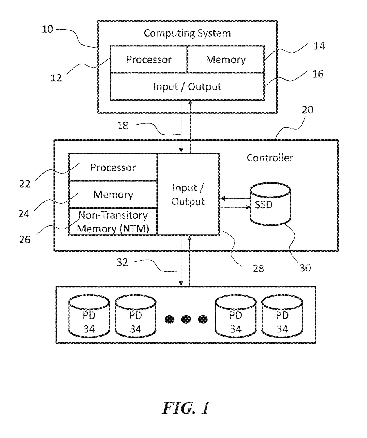
[0087]FIG. 1 shows an example diagram of a computing system connected to an example storage controller and physical storage drives. There is a computing system 10 with processors 12, memory 14, and an Input / Output (I / O) subsystem 16 allowing the computing system 10 to interface with many devices, including storage devices. In this example, the Input / Output subsystem 16 using a SAS interconnect 18 to interface with a controller 20 disclosed herein. The controller 20 has one or more processors 22, volatile memory 24, and Non-Transitory Memory (NTM) 26, and its own I / O subsystem 28.

[0088]The controller 20 also incorporates a private internal storage 30 (e.g., a solid-state drive) and additional private SAS interconnects 32 used to interface with one or more physical drives (PDs) 34.

[0089]The controller implementation shown in FIG. 1 is only one of many possibilities. Any storage interconnect technology such as SATA, Fibre Channel, or iSCSI is suitable for either the SAS interconnect...

example 2

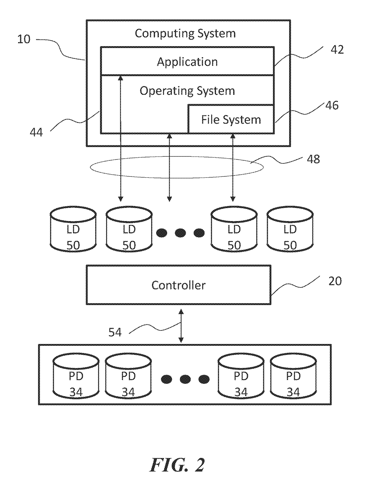
[0093]FIG. 2 illustrates a computing system 10, running software applications 42 on an operating system 44. The operating system 44 contains a file system 46. In some embodiments, the applications 42, operating system 44 and file system 46 all use block storage accesses 48 to utilize the logical storage drives 50.

[0094]The logical storage drives (LD) 50 are logical entities composed by the controller 20 from one or more PDs 34, which the controller 20 accesses using block storage accesses 54.

[0095]In some embodiments, logical storage drives 50 are individually identified by a unique logical unit number (e.g., 1, 2, 3, etc.).

[0096]The applications 42, operating system 44, and file system 46 cannot utilize the PDs 34 directly. The block storage accesses 48 of the applications 42, operating system 44, and file system 46 to the LDs 50 are transformed by the controller 20, resulting in a different set of block storage access54 to the PDs 34.

[0097]Support for a large number of logical sto...

example 3

e Write: Overview

[0106]FIG. 3A shows an overview of a data write process. As in 300, a computing system requests to write data to a logical block within the logical drive. When the controller receives the write request, its operation 302 decides wheter or not to store data in a NTM. If there is a NTM present and if the NTM has available space, the operation 302 takes the “Yes” path; the step 304 acknowledges write completion of the logical block, followed by applying a compression algorithm 306. At the check 302, if there is no NTM or the NTM is full, the controller takes the “No” path, where the controller directly applies a compression algorithm 306.

[0107]In some cases, the controller performs a check 308 to determine if the data has been compressed. If compressed, the operation 310 retains the compressed form of this logical block; otherwise, the operation 312 retains the original form of this logical block.

[0108]In some cases, a check 314 is made to determine if the controller i...


PUM


Abstract

Methods, devices, and media for improving data storage reliability and efficiency comprising: creating at least one logical storage drive comprising a plurality of logical blocks; mapping the at least one logical storage drive to at least one physical storage drive based on many-to-one mapping or one-to-many mapping, wherein the at least one physical storage drive comprises a plurality of physical blocks; and applying a compression algorithm to data held in one or more logical blocks, aggregating units of the data, and storing the units of the data into one or more physical blocks.

Description

BACKGROUND[0001]Due in large part to low data storage cost and ubiquitous communication technologies, demand for data storage is growing exponentially. Further, users of computing devices collect multimedia data much more often nowadays, so this demand is compounding. As such, efficient processing of data storage is advantageous.SUMMARY OF THE TECHNOLOGIES[0002]A physical storage drive is a complex piece of engineering, which includes multiple semiconductor devices, grained magnetic media platters, high speed read / write heads, spindle and servomotors, and a large firmware stack. When a drive has a defect, the entire drive is often treated as inoperable. However, the defect may be merely a firmware defect or a small problem in one sub-structure of the drive (e.g., a single read / write head, a portion of a platter surface, etc.); other sub-structures of the drive can still be utilized for data storage if a controller is enabled to circumvent these defects. To increase capacities of phy...

Claims


Application Information

Patent Timeline
IPC IPC(8): G06F3/06G06F12/1009G06F11/10
CPCG06F3/064G06F3/0619G06F3/065G06F3/0664G06F3/0665G06F3/0661G06F3/0685G06F12/1009G06F11/1044G06F2212/657G06F11/1076G06F3/0608G06F3/0616G06F3/0604G06F3/0614G06F3/0646
Inventor HUFF, GREGHEMPHILL, JOHN
Owner DIVERGENT STORAGE SYST INC
Why Eureka
Try Eureka