Length-adjustable con rod

a technology of connecting rods and con rods, which is applied in the direction of connecting rods, shafts, shafts, etc., can solve the problems of cavitation phenomena in the high-pressure chamber and negative pressure, and achieve the effect of small deflection of the stop element and simple control of the change of compression ratio

Active Publication Date: 2017-06-06
AVL LIST GMBH
View PDF16 Cites 13 Cited by
  • Summary
  • Abstract
  • Description
  • Claims
  • Application Information

AI Technical Summary

Benefits of technology

[0020]The transverse borehole is advantageously arranged in the upper third of the connecting rod which comprises the small-end of the connecting rod. This leads to especially small deflections of the stop element.
[0021]In order to enable simple control of the changes in the com

Problems solved by technology

The piston element can be lifted from its bottom position in the high-load phase, which

Method used


Image

  • Length-adjustable con rod
  • Length-adjustable con rod
  • Length-adjustable con rod

Examples


first embodiment

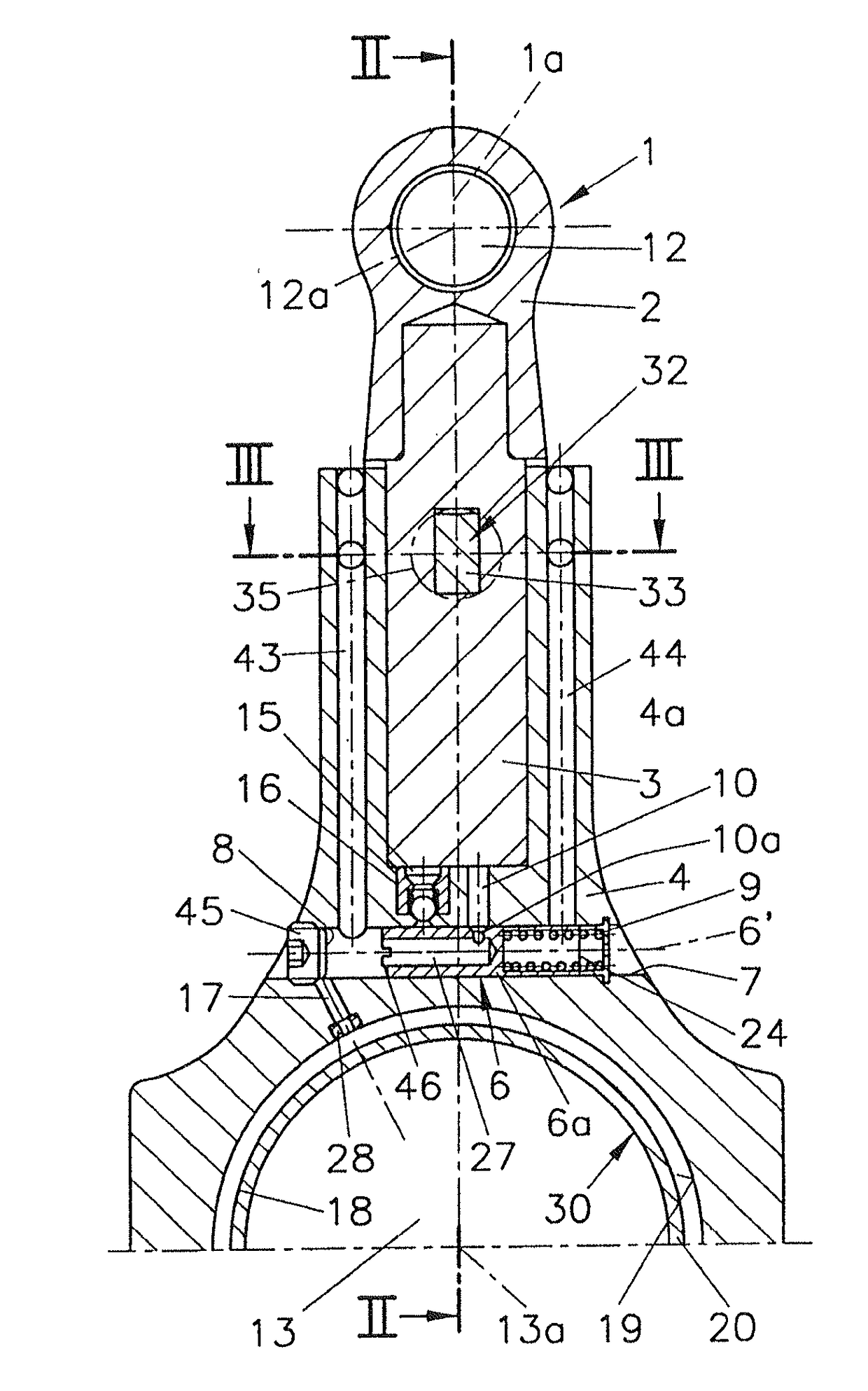
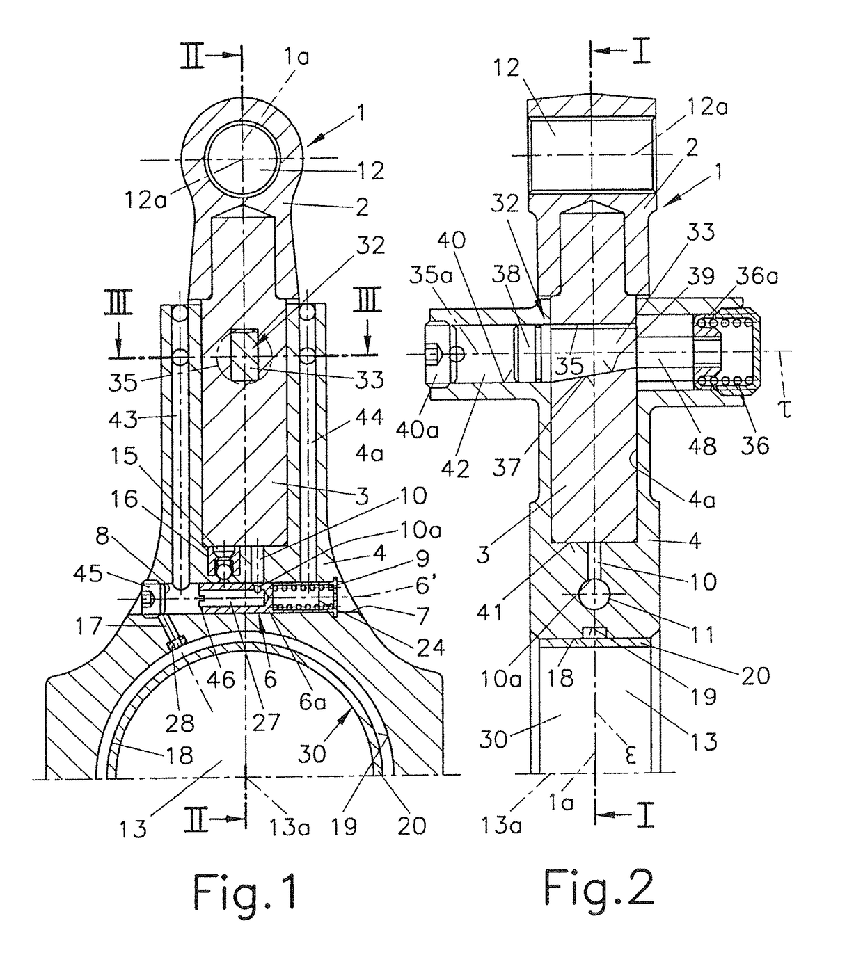
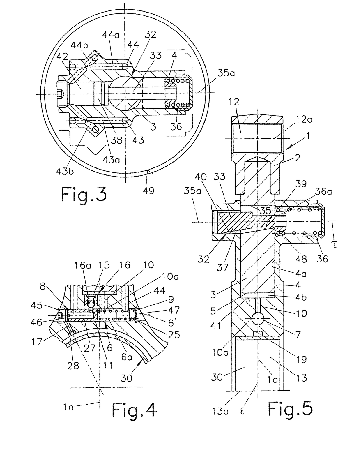
[0044]FIG. 1 and FIG. 2 show the connecting rod 1 in a first embodiment in a first position associated with a low compression ratio, and FIG. 4 and FIG. 5 in a second position associated with a high compression ratio.

[0045]The actuating piston 6a in the control valve 6 according to the first embodiment is arranged with a cylinder jacket 11 with an inner borehole 27 and arranged in the receiving borehole 7 together with a restoring spring 9. The receiving borehole 7 comprises a first stop 8 and a second stop 24. The first stop 8 is formed by a locking screw 45 and at least one projection 46 on the face end of the actuating piston 6a.

[0046]The actuating piston 6a is pressed in its receiving borehole 7 formed by a borehole transversely to the longitudinal axis 1a of the connecting rod 1 by the force of the restoring spring 9 against the first stop 8 at a low oil pressure level, as is shown in FIG. 4. The phrasing “borehole transversely to the longitudinal axis” comprises both borehole...

second embodiment

[0059]FIG. 10 and FIG. 11 shows a variant with a second embodiment for the control valve 6, which differs from the embodiment shown in FIG. 6 to FIG. 9 in such a way that the control valve 6 is arranged as a ball valve 60 with a valve ball 61 and a cylinder pin 63 which is axially displaceable in a receiving borehole 62 and which is displaceable together with the valve ball 61 by a restoring spring 64 to a first position and by oil pressure against the force of the restoring spring 64 to a second position. The first oil duct 10, which is formed by a pocket hole originating in the base of the high-pressure chamber 4b in which a stitch borehole to the receiving borehole 62 is situated, is located between the high-pressure chamber 4b and the receiving borehole 62. The stitch borehole opens into the receiving borehole 62 in which the axially displaceable cylinder pin 63 is arranged, which comprises a pin 65 at its end facing the valve ball 61 which acts on the valve ball 61. The receivi...


PUM


Abstract

The invention relates to a length-adjustable con rod (1) for a reciprocating piston engine, particularly an internal combustion engine, having at least a first and a second rod part (2, 4), wherein the two rod parts (2, 4) can be pushed together and/or inside one another in a telescoping manner, wherein the second rod part (4) forms a guide cylinder (4a) and the first rod part (2) a piston element (3) which can be pushed longitudinally in the guide cylinder (4a), wherein a high-pressure chamber (4b), into which at least one oil channel (10) opens, is clamped between the first and the second rod parts (2, 4). To enable the compression ratio to be adjusted in the simplest and most reliable manner possible, according to the invention the two rod parts (2, 4) can be fixed, by a locking device (32), relative to one another in at least one position, preferably corresponding to a minimum length of the con rod (1).

Description

BACKGROUND OF THE INVENTION[0001]Field of the Invention[0002]The invention relates to a length-adjustable connecting rod for a reciprocating piston engine, especially an internal combustion engine, comprising at least a first and a second rod part, which two rod parts can be pushed together and / or inside one another in a telescopic manner, wherein the second rod part forms a guide cylinder and the first rod part a piston element which is longitudinally displaceable in the guide cylinder, wherein a high-pressure chamber is spanned between the first and the second rod part, into which at least one first oil duct opens.[0003]The Prior Art[0004]DE 101 51 517 A1 describes a piston and connecting rod assembly of variable length for producing a variable compression ratio in an internal combustion engine, comprising a first part and a second part which are coupled to a length-changing mechanism which is accommodated between the parts. The length-changing mechanism comprises a spring washer ...

Claims


Application Information

Patent Timeline
IPC IPC(8): F02B75/04F16C7/06
CPCF16C7/06F02B75/045Y10T74/2151F16C2360/22
Inventor MELDE-TUCZAI, HELMUTHOEDL, BERNHARDZURK, ANDREASSCHOEFFMANN, WOLFGANG
Owner AVL LIST GMBH
Why Eureka
Try Eureka