Electrically rechargeable, metal anode cell and battery systems and methods

a metal anode cell and battery technology, applied in the direction of batteries, cell components, sustainable manufacturing/processing, etc., can solve the problems of high cost of existing battery systems, gas turbines are not as versatile or useful as true storage devices, and no single battery system is commercially successful in this application

Active Publication Date: 2017-06-13
EOS ENERGY TECH HLDG LLC
View PDF107 Cites 9 Cited by
  • Summary
  • Abstract
  • Description
  • Claims
  • Application Information

AI Technical Summary

Benefits of technology

[0007]The present invention provides a new electrically rechargeable metal anode system design and battery chemistry has been provided in accordance with various aspects of this invention. This metal anode cell design incorporates a substantial number of novel and previously unexplored chemical, materials, structural, and design changes. The various changes and modifications of this zinc anode battery system will be described in greater detail below. In some embodiments, this metal anode cell may be a zinc-air cell. The new battery system has been successfully electrically discharged and charged this new battery system over 1800 times with no evidence of air cathode degradation. Based on such results, a long operational life is expected. Some (or all) of the modifications listed herein may be combined to obtain cell performance with long cycle life that may make this zinc air system both affordable and practical.
[0087]In some embodiments, the electrolyte comprises an additive that prevents or minimizes chlorine gas and / or hypochlorite evolution during cell recharge.

Problems solved by technology

To date, no single battery system is commercially successful in this application.
One reason is the high cost of existing battery systems.
However, gas turbines are not as versatile or useable as true storage devices such as batteries.
A second reason is that current battery cycle life is too low, making true lifetime costs much higher than the initial battery cost.
Another reason is that many batteries (such as sodium-sulfur batteries) operate at elevated temperatures, contain hazardous chemicals, or may be subject to secondary detrimental chemical reactions such as those occurring in lithium based batteries.
In short, there is no current commercial battery technology that offers large scale battery size, suitable performance, and long discharge / charge cycle life at a commercially viable price and a viable service life for electricity providers.

Method used


Image

  • Electrically rechargeable, metal anode cell and battery systems and methods
  • Electrically rechargeable, metal anode cell and battery systems and methods
  • Electrically rechargeable, metal anode cell and battery systems and methods

Examples


Embodiment Construction

[0143]While preferable embodiments of the invention have been shown and described herein, it will be obvious to those skilled in the art that such embodiments are provided by way of example only. Numerous variations, changes, and substitutions will now occur to those skilled in the art without departing from the invention. It should be understood that various alternatives to the embodiments of the invention described herein may be employed in practicing the invention.

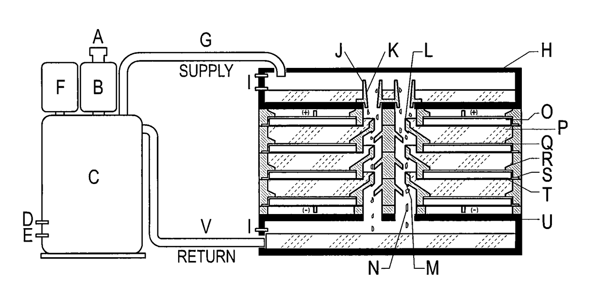
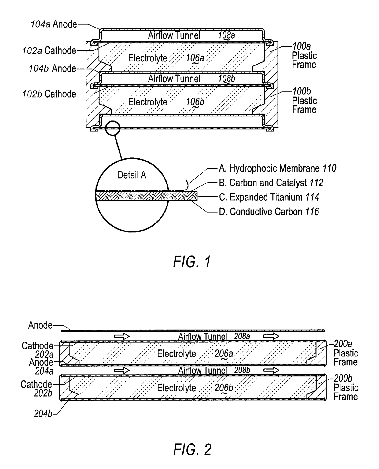
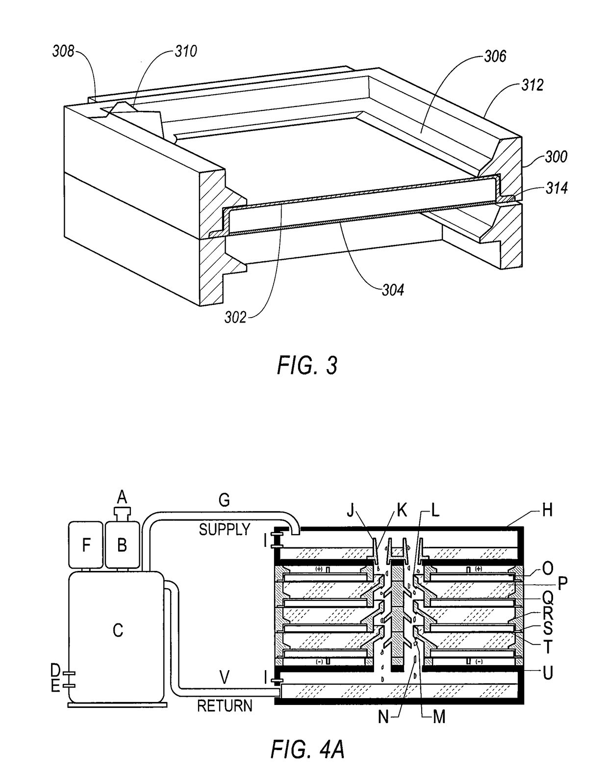
[0144]The invention provides electrically rechargeable metal anode cells and methods of assembling individual cells into battery systems. Various aspects of the invention described herein may be applied to any of the particular applications set forth below or for any other types of battery systems. The invention may be applied as a stand-alone system or method, or as part of a grid / utility system or a renewable energy storage system or method. It shall be understood that different aspects of the invention can be appreci...


PUM

PropertyMeasurementUnit
porosityaaaaaaaaaa
tensile strengthaaaaaaaaaa
mean diameteraaaaaaaaaa

Abstract

The invention provides for a fully electrically rechargeable metal anode battery systems and methods of achieving such systems. An electrically rechargeable metal anode cell may comprise a metal electrode, an air contacting electrode, and an aqueous electrolyte separating the metal electrode and the air contacting electrode. In some embodiments, the metal electrode may directly contact the liquid electrolyte and no separator or porous membrane is needed between the air contacting electrode and the electrolyte. Rechargeable metal anode cells may be electrically connected to one another through a centrode connection where a metal electrode of one cell and an air contacting electrode of a second cell are electrically connected. Air tunnels or pathways may be provided between individual metal anode cells arranged in a stack. In some embodiments, an electrolyte flow management system may also be provided to maintain liquid electrolyte at constant levels during charge and discharge cycles.

Description

CROSS REFERENCE TO RELATED APPLICATION[0001]This U.S. non-provisional application claims the benefit of PCT application number PCT / US2012 / 069677, filed on Dec. 14, 2012, which claims the benefit of U.S. provisional application ser. No 61 / 570,716, which was filed on Dec. 14, 2011. The entire contents of these applications are incorporated by reference herein.BACKGROUND OF THE INVENTION[0002]The combination of an aging electrical grid infrastructure and integration of intermittent generation sources from large scale renewable energy resources (such as wind, solar, and ocean waves) has increased the critical need to develop effective energy storage technologies to achieve power supply stability of the grid and shift electric power supplies during peak and off-peak periods. Electricity providers are looking for ways to add clean power to the grid, prevent power outages and manage peak loads in a cost effective way without adding additional generating capacity. Storage batteries are crit...

Claims


Application Information

Patent Timeline
Patent Type & Authority Patents(United States)
IPC IPC(8): H01M12/08H01M4/58H01M4/66H01M4/86H01M4/90H01M10/26H01M10/28H01M12/06H01M4/52H01M4/50H01M4/48H01M2/36H01M10/04H01M4/46H01M4/24H01M4/36H01M2/38H01M4/38H01M4/42
CPCH01M12/08H01M4/24H01M4/362H01M4/38H01M4/42H01M4/46H01M4/48H01M4/50H01M4/52H01M4/58H01M4/5825H01M4/661H01M4/663H01M4/667H01M4/8615H01M4/8631H01M4/8647H01M4/8657H01M4/8663H01M4/90H01M4/9016H01M4/9041H01M10/0413H01M10/0418H01M10/0486H01M10/26H01M10/281H01M10/282H01M12/065H01M12/085H01M4/386H01M10/0445H01M2004/8689H01M2220/10Y02P70/50Y02E60/10
Inventor AMENDOLA, STEVENBINDER, MICHAELBLACK, PHILLIP J.SHARP-GOLDMAN, STEFANIEJOHNSON, LOISKUNZ, MICHAELOSTER, MICHAELCHCIUK, TESIAJOHNSON, REGAN
Owner EOS ENERGY TECH HLDG LLC
Why Eureka
Try Eureka