
Method and apparatus for network anomaly detection

a network anomaly and anomaly detection technology, applied in the field of network anomaly detection methods and apparatuses, can solve the problems of significant shift in network traffic and network capacity, difficult automation process, impracticality of constant human monitoring, etc., and achieve the effect of accurate detection of network anomalies

Active Publication Date: 2017-06-13
WISCONSIN ALUMNI RES FOUND
View PDF8 Cites 4 Cited by
  • Summary
  • Abstract
  • Description
  • Claims
  • Application Information

AI Technical Summary

Benefits of technology

The invention is a network anomaly detector that combines two simple and robust detection techniques. The first technique looks at the variability of network statistics, while the second technique looks for change in the interrelationship between multiple time measures of the network. This results in an accurate detection of network anomalies that is resistant to false alarms. The detector provides a simple but accurate representation of variability over multiple time scales, and is sensitive to extremely short time window anomalies while being robust against false triggering even with extremely short time windows. The detector also adapts to heuristic behavior and uses compact historical descriptions of network behavior that may be practically stored and processed.

Problems solved by technology

Network anomalies may also reflect innocent activities that should nevertheless be monitored, including “flash crowd” events occurring because of unexpected and episodic demand for particular data, for example, an unexpectedly popular sporting event sourced from one server to many subscribers, or “node failures” including generally network hardware, network media, or network software causing a significant shift in network traffic and network capacity.
Automating the process of detecting network anomalies is important because of the large amount of network data and the impracticality of constant human monitoring of network events.
Nevertheless, this automation process is difficult, particularly given the high variability of normal network traffic.
Simple thresholding techniques, when adjusted to limit “false positive” detections, may be unable to detect important anomalies that make minor changes in fundamental network statistics.
The use of more complex models, for example, neural nets that model normal network behavior, run the risk of bias toward “known” anomalies at the expense of important unknown or unexpected anomalies.
Highly sophisticated automated detection techniques that require large amounts of data storage or computer power, may be impractical for routine network analysis.

Method used


Image

  • Method and apparatus for network anomaly detection
  • Method and apparatus for network anomaly detection
  • Method and apparatus for network anomaly detection

Examples


Embodiment Construction

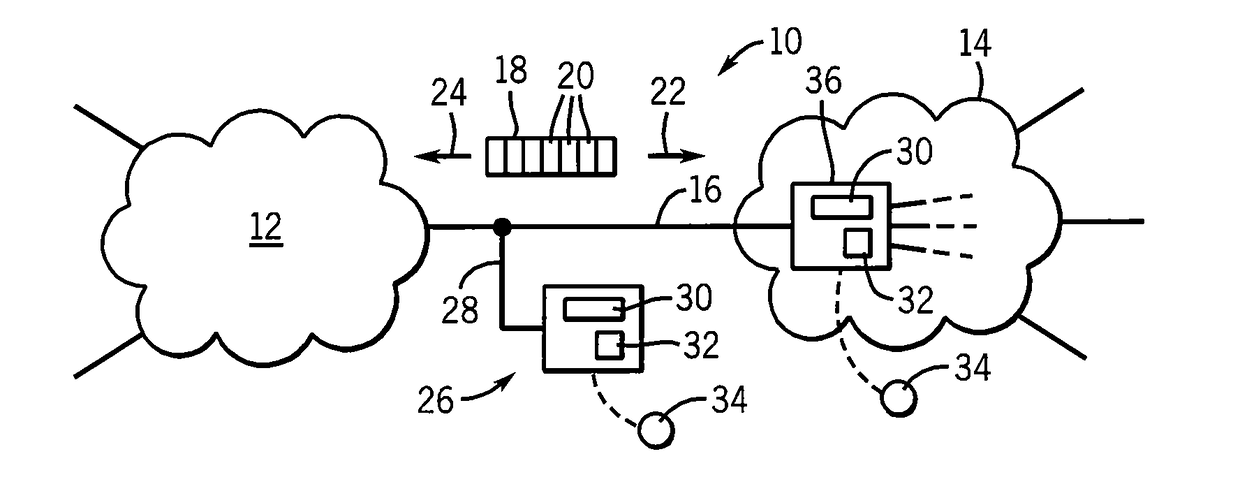
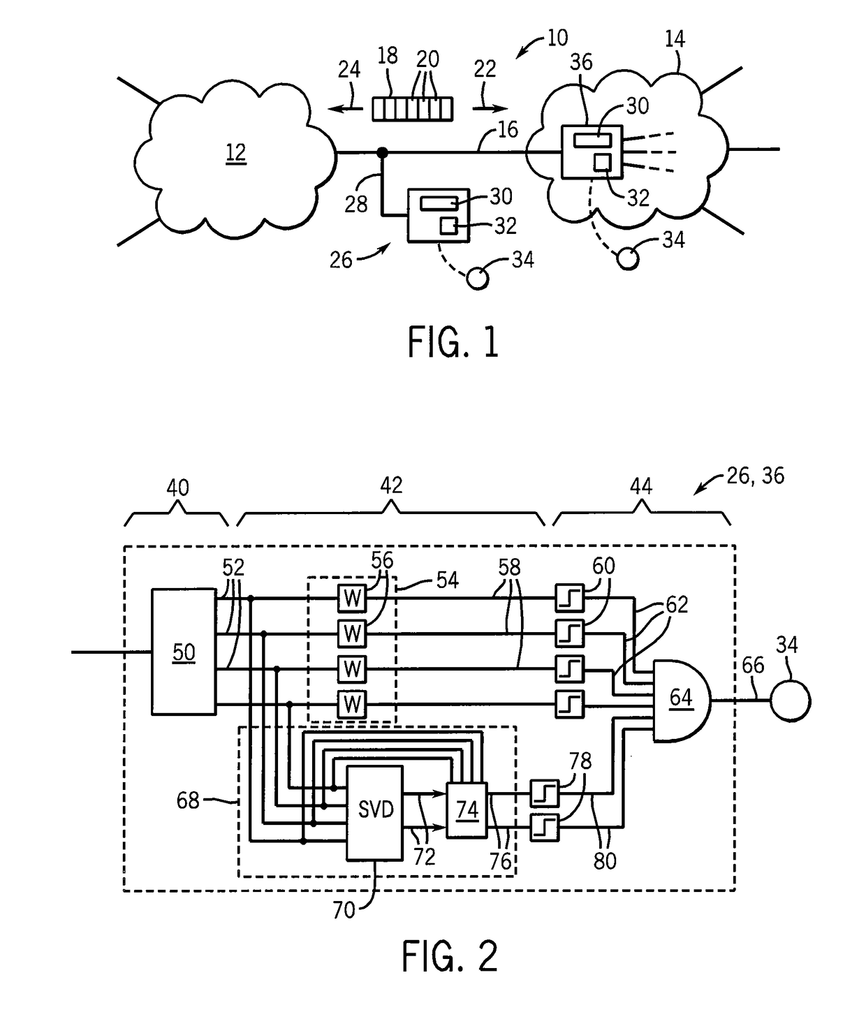
[0042]Referring now to FIG. 1, a computer network 10, for example the Internet, may include a variety of smaller networks 12 and stub networks 14 joined by one or more network lines 16. A typical network line 16 may be, for example, an IEEE 802.1q gigabyte Ethernet trunk.

[0043]The network line 16 may communicate data packets 18 between the networks 12 and 14, both in an incoming direction 22 from network 12 to network 14 and in an outgoing direction 24 from network 14 to network 12. Each packet 18 is comprised of variable numbers of bits 20.

[0044]A standalone network monitor 26 may provide a tap 28 connecting the standalone network monitor 26 to the network line 16 to read the packets 18 transmitted thereon. The standalone network monitor 26 may include a dedicated processor 30 operating to execute a stored program 32 to implement the network traffic anomaly detector of the present invention and to provide an alert output 34 to an operator or response system. The alert output may be...


PUM


Abstract

A network anomaly detector evaluates two complementary measurements of network statistics, a time variation and correlation among those statistics, to provide an extremely robust detection of network anomalies. In one embodiment, the variability and correspondence are compared against historically derived thresholds to provide for a system that accommodates to local network conditions and evolving network qualities.

Description

CROSS-REFERENCE TO RELATED APPLICATIONS[0001]This application claims the benefit of PCT Application No. PCT / US07 / 85894, filed Nov. 29, 2007, and U.S. provisional application 60 / 867,733, filed Nov. 29, 2006, which are hereby incorporated by reference.STATEMENT REGARDING FEDERALLY SPONSORED RESEARCH OR DEVELOPMENT[0002]This invention was made with United States government support awarded by the following agencies: NIH GM072000 and NSF 0085984. The United States government has certain rights in this invention.BACKGROUND OF THE INVENTION[0003]The present invention relates to monitoring the transmission of network data, for example, on the Internet, and, particularly to, a monitoring system that provides improved detection of network anomalies.[0004]Computer networks, such as the Internet, transmit data among computers over a variety of different communication media (e.g., electrical cable, fiber optic cable) joined together by different network switches or routers. Common data transmiss...

Claims


Application Information

Patent Timeline
Patent Type & Authority Patents(United States)
IPC IPC(8): H04L12/26H04L12/24H04L29/06
CPCH04L41/064H04L41/142H04L63/1425H04L43/045H04L43/16
Inventor BARFORD, PAUL R.KLINE, JEFFERY THOMASNAM, SANGNAMPLONKA, DAVID JOHNRON, AMOS
Owner WISCONSIN ALUMNI RES FOUND
Learn More