Analytical laser ablation of solid samples for ICP, ICP-MS and FAG-MS analysis

a laser ablation and solid sample technology, applied in the field of analytical laser ablation of solid sample for icp, icpms and fagms analysis, to achieve the effect of reducing demagnification and high analytical sensitivity

Inactive Publication Date: 2017-07-04
HUGHES STEVEN K +1
View PDF13 Cites 5 Cited by
  • Summary
  • Abstract
  • Description
  • Claims
  • Application Information

AI Technical Summary

Benefits of technology

[0028]Invention optical decoupling of the two paths is desirable for UV laser ablation to allow separate optical optimization of the invention laser path and the invention white light camera view. (A prior art “coupled path” does not permit this). The invention UV laser objective lens (8) focuses only the UV laser light, and does not affect the invention white light camera view which may then be separately focused with an invention high quality achromatic visible lens (21), optimized separately for the invention camera (22), and thereby eliminating chromatic aberration from the camera view (22, 28). This invention allows the best laser ablation characteristics to occur (24) simultaneously with the best quality observer (camera) image (22).
[0077]In an alternate embodiment, the compliant seal is an inflatable and deflatable bladder which may be deflated for change of sample and inflated to re-establish perimeter seal around the sample. In this embodiment, the samples are presented sequentially in an x,y sliding tray or rotary platter, or R-theta platter during inflate / deflate cycles to effect an inexpensive automatic sample changer.

Problems solved by technology

(A prior art “coupled path” does not permit this).

Method used


Image

  • Analytical laser ablation of solid samples for ICP, ICP-MS and FAG-MS analysis
  • Analytical laser ablation of solid samples for ICP, ICP-MS and FAG-MS analysis
  • Analytical laser ablation of solid samples for ICP, ICP-MS and FAG-MS analysis

Examples


Embodiment Construction

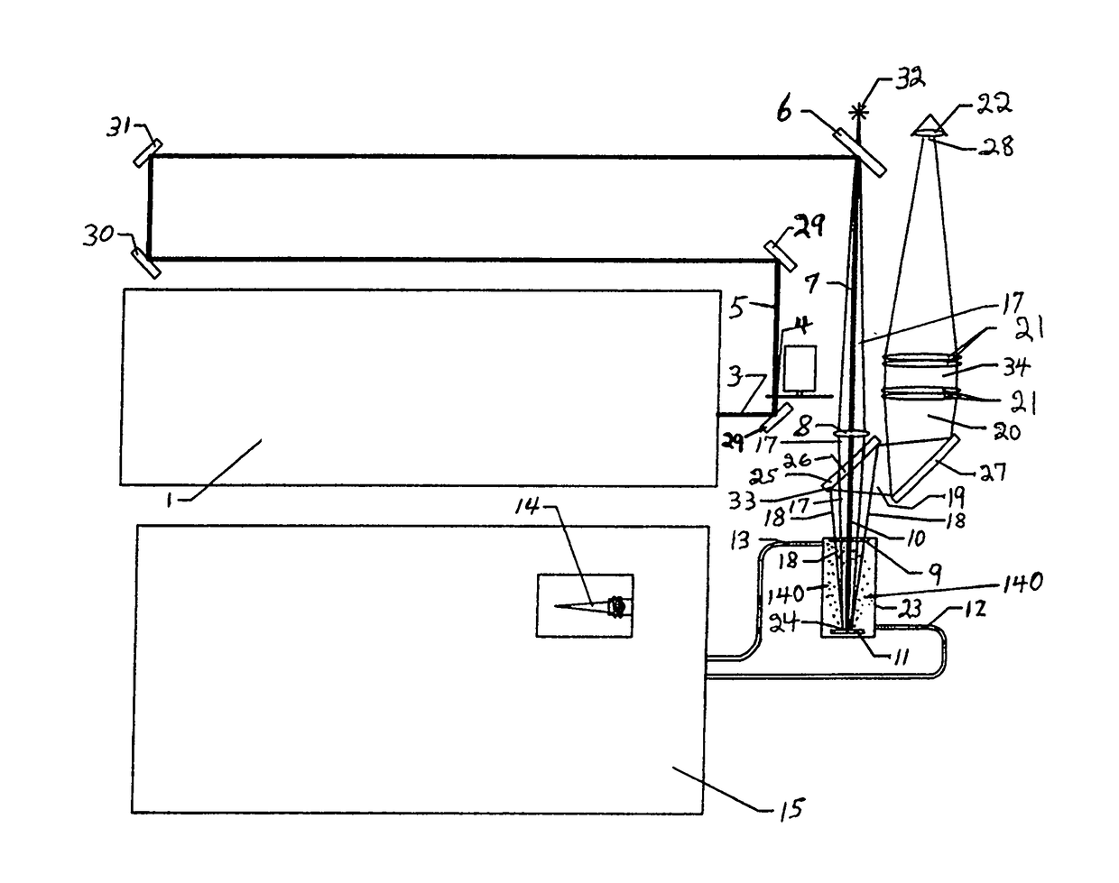
[0110]Referring to FIGS. 2A-B, a preferred embodiment of the invention involves a mirror-with-hole (25, 26) positioned below long focal length invention laser objective lens (8). The invention mirror-with-hole (25, 26) allows a focused invention UV laser beam (7, 10) to pass (unaltered) through the hole (26) to the solid material surface (11) while the invention observer (22) visible “white light view” (28) of said solid material surface is obtained off axis with the invention mirror perimeter (33) essentially concentrically surrounding the hole (26) and said UV laser beam (7, 10) passing through said hole (26). The advantage of this invention is that a final delivery segment (to the solid sample surface (11)) of the invention UV laser beam (10) is coaxially superimposed with an initial segment (18) of the invention visible “white light” observer view (22) with both invention paths sharing a single coincident focal plane (24), which is the “image” plane of the invention laser object...


PUM

PropertyMeasurementUnit
diameteraaaaaaaaaa
diameteraaaaaaaaaa
sizeaaaaaaaaaa

Abstract

The present invention facilitates improvements in laser ablation of solid samples to be analyzed by an external inductively coupled plasma (ICP) emission spectrometer, ICP / mass-spectrometer (ICP-MS), or flowing afterglow (FAG) mass spectrometer (FAG-MS) for elemental analysis (ICP and ICP-MS) or molecular analysis (FAG-MS). A novel invention mirror-with-hole beam combiner eliminates chromatic aberration in the invention sample view and allows rad-hardening the laser ablation invention for use in a radiation hot cell for analysis of high activity nuclear waste. Many other novel invention rad-hardening attributes facilitate a comprehensive rad-hardened laser ablation system (the world's first). In other embodiments, invention novelties include unusually large homogeneous focused laser spot diameters, unusually long laser objective lens focal length, wide range operationally variable laser path length with built-in re-alignment, operationally variable demagnification ratio and diameter of the focused laser spot, the use of significantly higher powered SMR lasers in a large spot diameter to facilitate high sensitivity bulk analysis of solid samples, a demountable and gravitationally self-sealing stack assembly laser ablation cell, and the world's first auto-samplers (mechanized sample changers) for analytical laser ablation.

Description

CROSS REFERENCE TO RELATED APPLICATIONS[0001]This application is a CIP of U.S. application Ser. No. 13 / 573,554 filed Sep. 24, 2012 (now U.S. Pat. No. 9,079,268) and therevia is a CIP of U.S. application Ser. No. 12 / 283,698 filed Sep. 14, 2008 (now U.S. Pat. No. 8,274,735) and therevia claims benefit of U.S. Provisional Application Ser. Nos. 60 / 993,795 and 61 / 134,136 filed on Sep. 14, 2007 and Jul. 7, 2008, respectively. Said U.S. application Ser. No. 13 / 573,554, said U.S. application Ser. No. 12 / 283,698, and said U.S. Provisional Application Nos. 60 / 993,795 and 61 / 134,136 are hereby incorporated by reference.FIELD OF THE INVENTION[0002]This invention relates to 1.) improved optical viewing of ultraviolet (hereafter “UV”) laser ablation processes involving solid materials, and to 2.) high sensitivity analysis of solid materials by analytical UV laser ablation, and to 3.) large spot bulk analysis of solid materials by analytical UV laser ablation, and to 4.) automated (mechanized) sam...

Claims


Application Information

Patent Timeline
Patent Type & Authority Patents(United States)
IPC IPC(8): G02B21/26B23K26/40B23K26/046B23K26/14
CPCB23K26/40B23K26/046B23K26/1405G01N21/718G02B5/0891G02B27/14B23K26/142
Inventor HUGHES, STEVEN K.FRY, ROBERT C.
Owner HUGHES STEVEN K
Why Eureka
Try Eureka