Soft-switched bidirectional buck-boost converters

a converter and soft-switching technology, applied in the direction of electric variable regulation, process and machine control, instruments, etc., can solve the problems of increasing the size of the converter, ccm operations in high-voltage, high-power buck and boost converters at high frequencies, and igbt implementation is limited to a relatively low frequency, so as to reduce switching losses, minimize reverse-recovery losses, and reduce switching losses

Active Publication Date: 2017-07-11
DELTA ELECTRONICS INC
View PDF10 Cites 11 Cited by
  • Summary
  • Abstract
  • Description
  • Claims
  • Application Information

AI Technical Summary

Benefits of technology

[0008]The present invention provides active-snubber methods that offer reduced switching losses in the semiconductor switches of a bidirectional buck-boost converter. Specifically, these methods reduce switching losses by soft-switching all semiconductor switches. In a buck-boost converter of the present invention, each rectifier is turned off with a controlled turn-off rate in its current to minimize reverse-recovery loss, the power-controlling switch is turned on with zero-voltage switching (ZVS), and the auxiliary switch in the active snubber is turned off with zero-current switching (ZCS). Because of the fully soft-switched operation, converters of the present invention exhibit improved efficiency and EMI performance, as compared to their conventional “hard”-switched counterparts. The present invention also enables using semiconductor switches with relative slow antiparallel diodes (rectifiers) at high frequencies.
[0009]According to one embodiment of the present invention, two active-snubber soft-switching cells reduce switching losses in a bidirectional buck-boost converter. One soft-switching cell is active during a buck-mode operation, while the other soft-switching cell is active during a boost-mode operation. Each soft-switching cell includes an active switch (“snubber switch”) coupled in series with a snubber inductor, a two-winding transformer, and a reset-voltage circuit. In every switching cycle, the snubber switch is turned on prior to turning on the corresponding switch of the buck-boost converter. When the snubber switch is on, the snubber inductor controls the turn-off rate of the corresponding rectifier to reduce its reverse-recovery loss and to create a condition for zero-voltage switching in the corresponding switch. The transformer provides a reset voltage for the snubber inductor current and creates a condition for a zero-current turn-off in the snubber switch, while the reset-voltage circuit resets the magnetizing energy of the transformer.
[0010]According to one embodiment of this invention, the snubber inductor is common to both soft-switching cells (i.e., only one snubber inductor is used). In another embodiment of the present invention, both soft-switching cells share a common snubber inductor, a transformer, and a reset-voltage circuit. The component count of a soft-switching cell can be further reduced by implementing the snubber inductor from the leakage current of the transformer.

Problems solved by technology

Because a battery's operating voltage range depends on the battery's state of charge, achieving high efficiency across the entire operating voltage range of a battery is a major design challenge in bidirectional converter designs.
As described in U.S. Pat. No. 5,736,842, entitled “Techniques for Reducing Rectifier Reverse-Recovery-Related Losses in High-Voltage High Power Converters,” by M. M. Jovanovic (“the '842 patent”), the major limitations of CCM operations in high-voltage, high-power buck and boost converters at high frequencies are related to switching losses caused by reverse-recovery in the rectifiers and capacitive turn-on switching losses in the switches due to “hard” switching.
The IGBT implementation is limited to a relatively low frequency, due to the relatively limited switching speed of an IGBT, which increases the size of the converter.
However, at this time, the SiC or GaN switch implementation is not attractive, primarily due to increased cost, as well as a lack of sufficient in-the-field reliability data.

Method used


Image

  • Soft-switched bidirectional buck-boost converters
  • Soft-switched bidirectional buck-boost converters
  • Soft-switched bidirectional buck-boost converters

Examples


Embodiment Construction

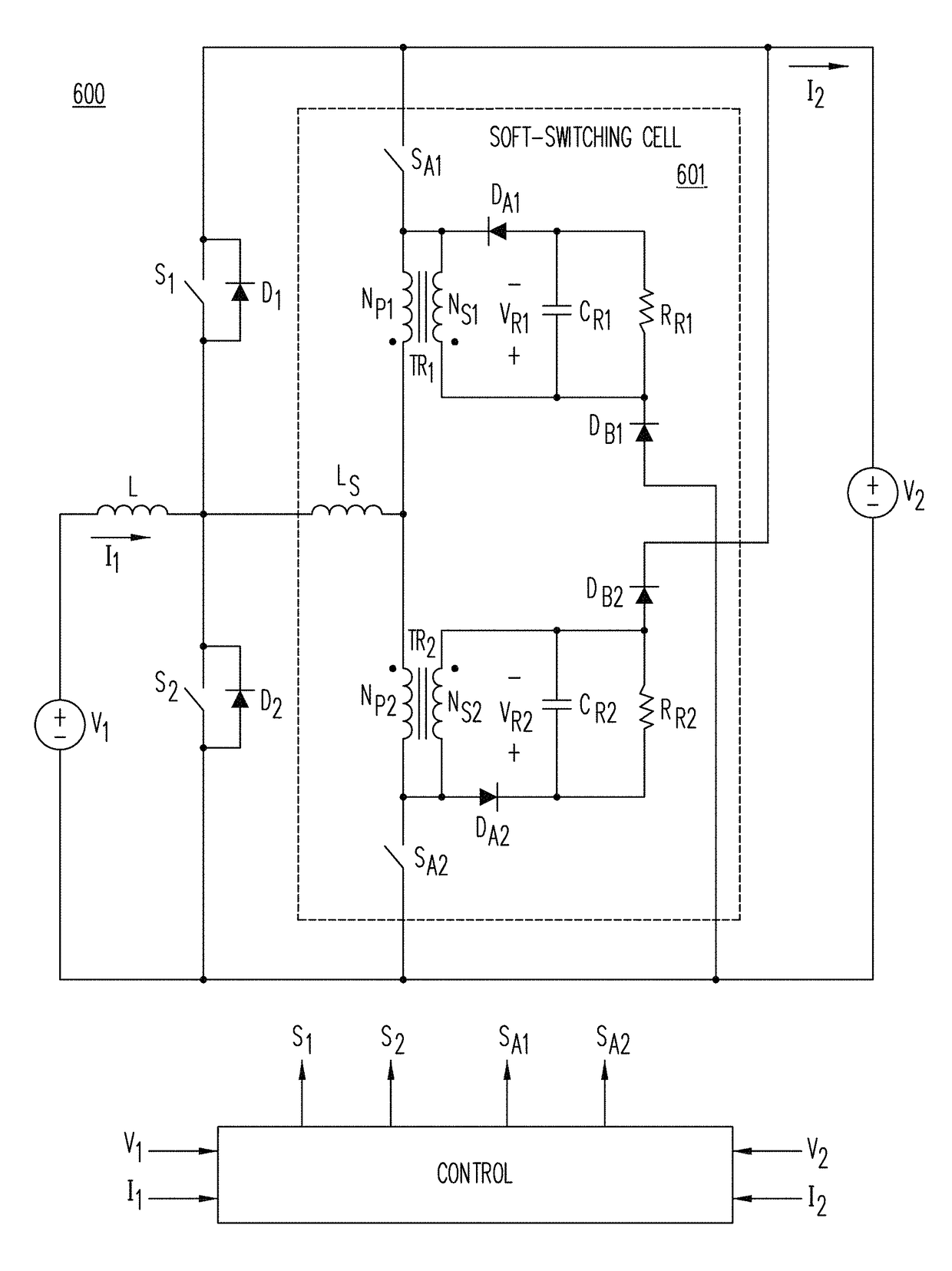
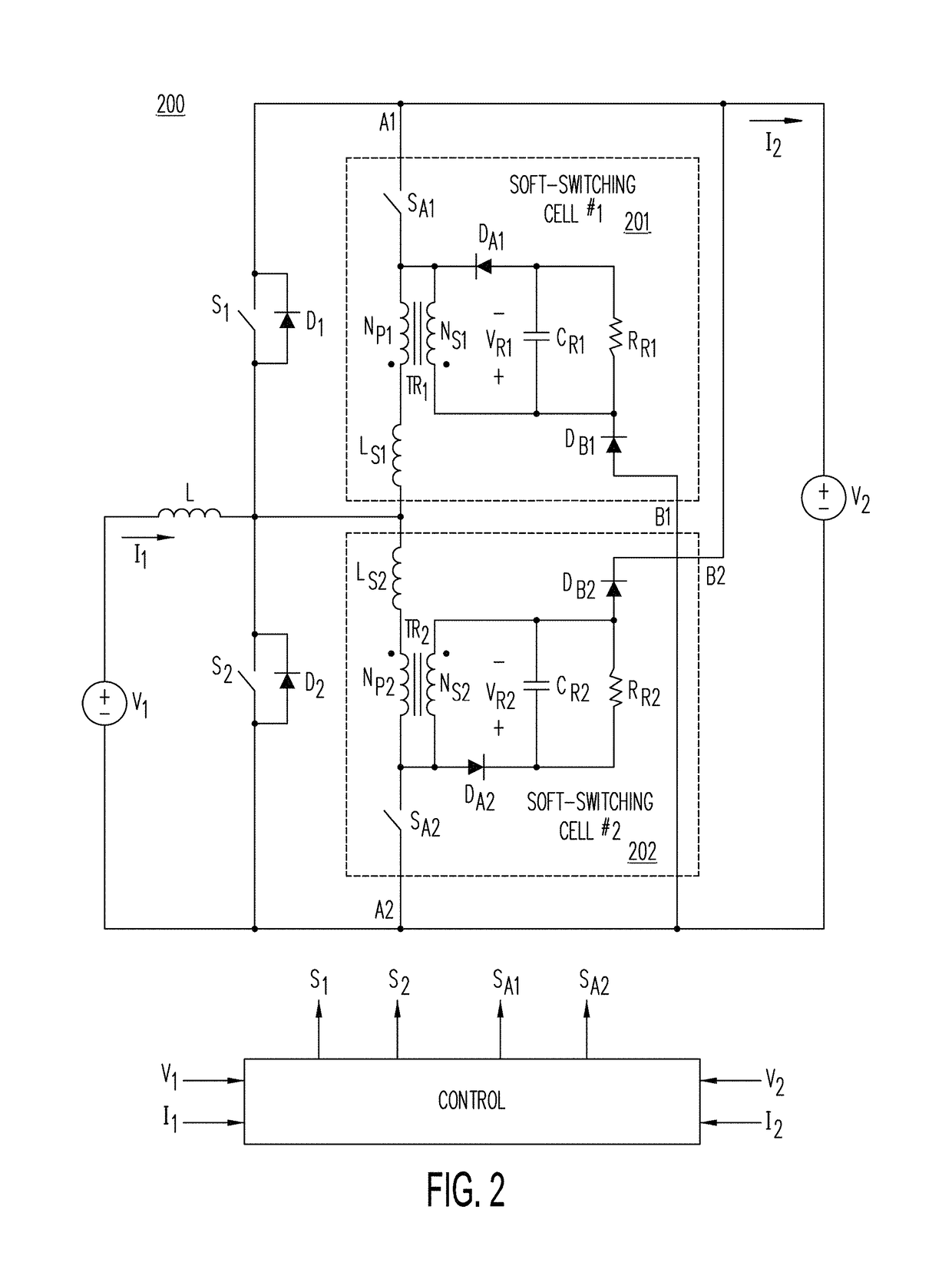
[0032]FIG. 2 shows soft-switched, bidirectional buck-boost converter 200, in accordance with an exemplary embodiment of the present invention. As shown in FIG. 2, buck-boost converter 200 includes soft-switching cells 201 and 202, each including: (a) active switch SA, (b) inductor LS, (c) isolation transformer TR, and (d) a reset-voltage circuit formed by diode DA, capacitor CR, resistor RR and diode DB. To distinguish the elements in soft-switching cells 201 and 202, the circuit elements of soft-switching cell 201 and the circuit elements of soft-switching cell 202 are further subscripted by the reference numeral ‘1’ and ‘2,’ respectively. In FIG. 2, switches SA1 and SA2 are unidirectional current switches that can carry current only in one direction. When a bidirectional current switch (e.g., a MOSFET) is used, a rectifier in series with the switch is provided to prevent conduction of the switch's antiparallel diode. Voltage sources V1 and V2 may be implemented by any kind of DC p...


PUM


Abstract

A bidirectional buck-boost converter includes at least one soft-switching cell to reduce switching losses by providing soft-switching of all semiconductor devices. A soft-switching cell comprises an active switch coupled in series with an inductor, a two-winding transformer, and a reset-voltage circuit. The soft-switching cells enable the buck and boost rectifiers to turn off with a controlled turn-off rate of their current to minimize their reverse-recovery losses, the power-controlling buck and boost switch to turn on with zero-voltage switching (ZVS), and the switch of the soft-switching cell to turn off with zero-current switching (ZCS).

Description

BACKGROUND OF THE INVENTION[0001]1. Field of the Invention[0002]This invention relates to the buck-boost converters, and more particularly, to buck-boost converters with soft switching in all of their semiconductor components.[0003]2. Description of the Related Art[0004]Bidirectional converters are increasingly being used in power systems with energy-storage capabilities (e.g., “smart-grid” and automotive applications), where they condition charging and discharging of energy-storage devices (e.g., batteries and super-capacitors). For example, in automotive applications, isolated bidirectional converters are used in electric vehicles (EVs) to provide bidirectional energy exchange between the high-voltage (HV) battery and the low-voltage (LV) battery, while non-isolated bidirectional converters are typically employed to optimize the traction inverter performance by pre-regulating its input voltage, as well as provide energy regeneration. Because a battery's operating voltage range dep...

Claims


Application Information

Patent Timeline
Patent Type & Authority Patents(United States)
IPC IPC(8): H02M3/335
CPCH02M3/33546H02M3/1582Y02B70/10H02M1/0058
Inventor JANG, YUNGTAEKJOVANOVIĆ, MILAN M.
Owner DELTA ELECTRONICS INC
Why Eureka
Try Eureka