Systems and methods for depressurizing a fuel tank

a technology of fuel tank and depressurization method, which is applied in the direction of valve operating means/release devices, machines/engines, vehicle sub-unit features, etc., can solve the problems of increasing power consumption, increasing maintenance costs, and vapors from running loss and diurnal temperature cycles not being transferred into the fuel vapor canister, so as to reduce the release of fuel vapors

Active Publication Date: 2017-07-18
FORD GLOBAL TECH LLC
View PDF11 Cites 3 Cited by
  • Summary
  • Abstract
  • Description
  • Claims
  • Application Information

AI Technical Summary

Benefits of technology

[0002]Vehicle fuel systems include evaporative emission control systems designed to reduce the release of fuel vapors to the atmosphere. For example, vaporized hydrocarbons (HCs) from a fuel tank may be stored in a fuel vapor canister packed with an adsorbent which adsorbs and stores the vapors. At a later time, when the engine is in operation in a hybrid vehicle, the evaporative emission control system allows the vapors to be purged into the engine intake manifold for use as fuel.
[0003]The fuel vapor canister in the hybrid vehicle may primarily store refueling vapors. Further, vapors from running loss and diurnal temperature cycles may not be transferred into the fuel vapor canister and may be contained within the fuel tank. Accordingly, pressure may build in the fuel tank and a higher pressure may exist within the fuel tank. When a vehicle operator indicates a demand to refuel the hybrid vehicle, the fuel cap may be locked until venting of the fuel tank is allowed to sufficiently reduce tank pressure. As such, the fuel cap may be unlocked only after the tank pressure is below a threshold pressure protecting the vehicle operator from being sprayed with fuel vapor.
[0004]Previously disclosed systems include a single fuel tank isolation valve (FTIV) between the fuel tank and the fuel vapor canister. The FTIV may be a solenoid valve that is normally closed but the FTIV may be opened to prepare the fuel tank for refueling. However, a constant voltage supply may be provided to energize the FTIV to open and enable depressurization of the fuel tank. As such, the constant supply of voltage to the FTIV may increase power consumption and lead to a rise in maintenance costs. Accordingly, the FTIV may be replaced with a latchable refueling valve. The latchable refueling valve may reduce power consumption but may not provide a sufficient depressurization rate during certain conditions. For example, in hot weather conditions, the fuel tank may be at a higher pressure and depressurization via the latchable refueling valve may take a longer time. Specifically, the vehicle operator may have to wait for a longer time until the fuel tank is ready for refueling.

Problems solved by technology

Further, vapors from running loss and diurnal temperature cycles may not be transferred into the fuel vapor canister and may be contained within the fuel tank.
As such, the constant supply of voltage to the FTIV may increase power consumption and lead to a rise in maintenance costs.
The latchable refueling valve may reduce power consumption but may not provide a sufficient depressurization rate during certain conditions.
For example, in hot weather conditions, the fuel tank may be at a higher pressure and depressurization via the latchable refueling valve may take a longer time.
Specifically, the vehicle operator may have to wait for a longer time until the fuel tank is ready for refueling.
The tank pressure control valve and the latchable refueling valve may be normally closed such that fluidic communication between the fuel tank and the fuel vapor canister is impeded.
Further, since the latchable refueling valve is adjusted to the unlatched open position only after the pre-determined duration, the latchable refueling valve may not receive continuous voltage through the entire duration of depressurization of the fuel tank.

Method used


Image

  • Systems and methods for depressurizing a fuel tank
  • Systems and methods for depressurizing a fuel tank
  • Systems and methods for depressurizing a fuel tank

Examples


Embodiment Construction

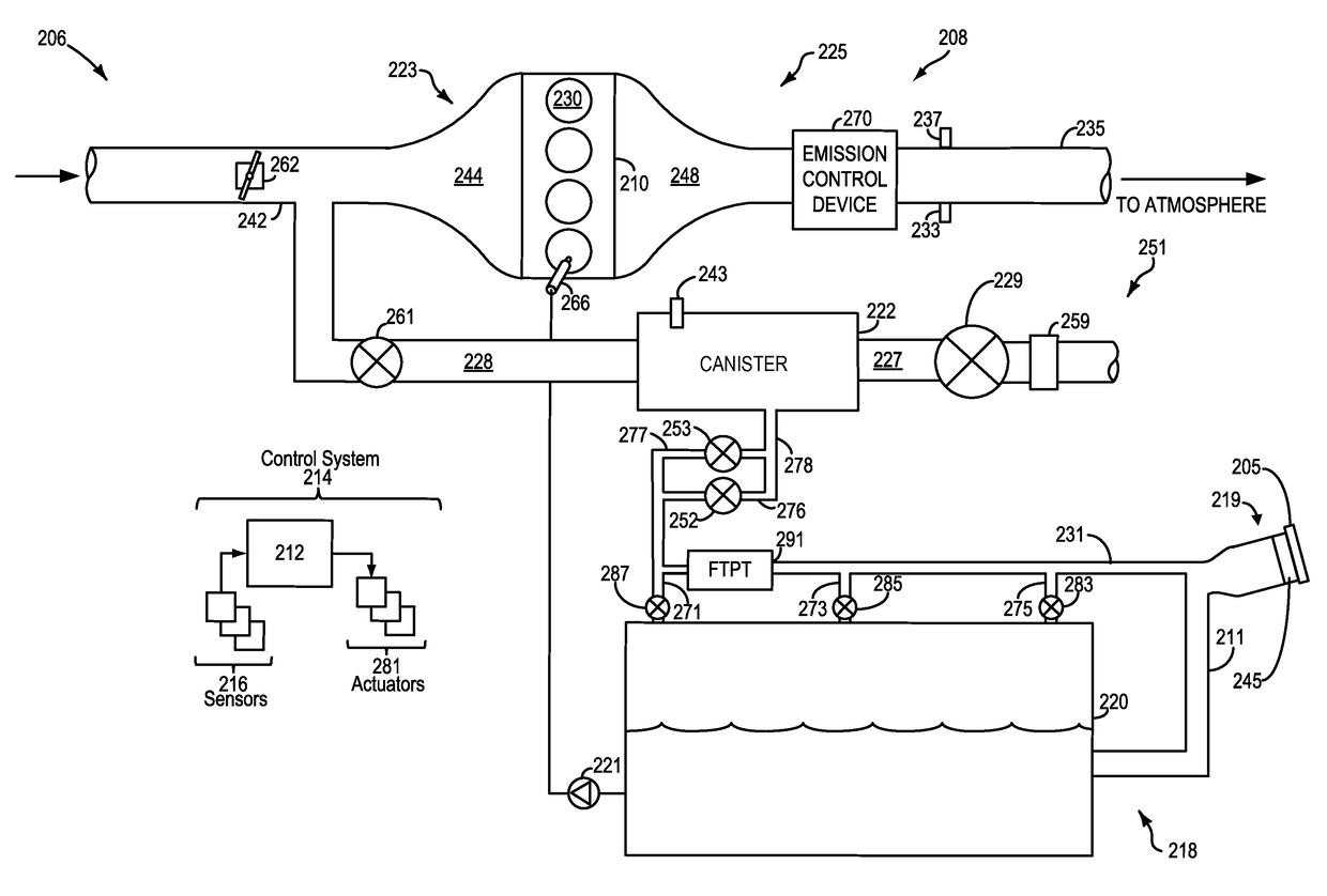
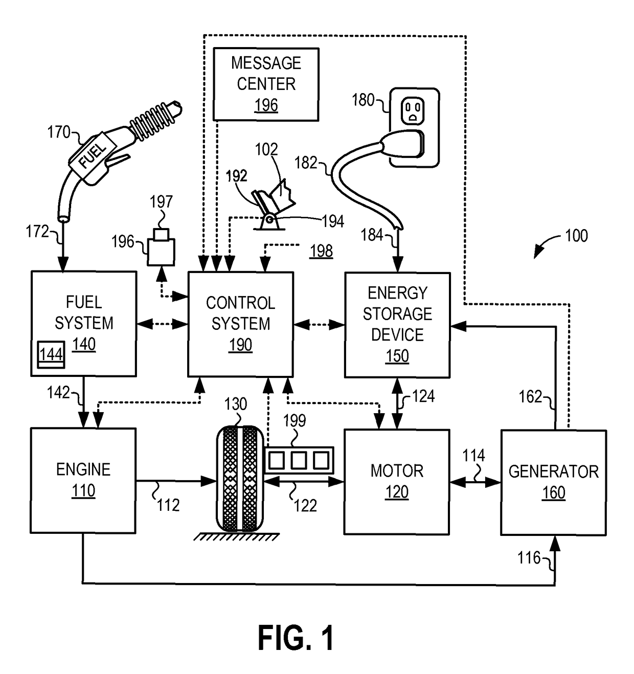
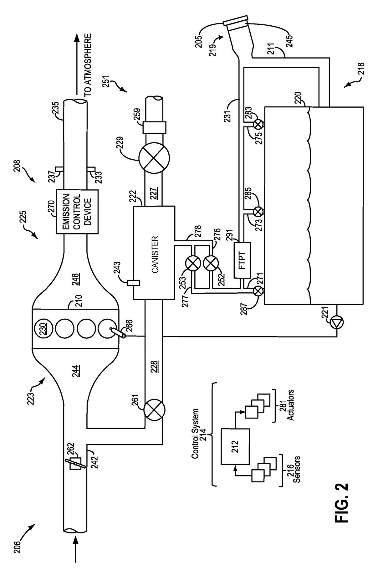
[0019]The following description relates to systems and methods for depressurizing a fuel tank via a latchable refueling valve. The fuel tank may be included in a vehicle, such as a hybrid electric vehicle, as shown in FIG. 1. The vehicle may include a fuel system and an evaporative emissions system, as shown in FIG. 2. The fuel system may be coupled to the evaporative emissions system via each of a tank pressure control valve and the latchable refueling valve (FIG. 3). The latchable refueling valve may be adjusted from a latched closed position to a latched open position via a first pulse of voltage (FIG. 4). Further, the latchable refueling valve may be adjusted from the latched open position to the latched closed position by a second pulse of voltage (FIG. 5). Furthermore, the latchable refueling valve may be held at a more open position relative to the latched open position by applying a continuous voltage (FIG. 6). Fuel pressure within the fuel tank may rise substantially due to...


PUM


Abstract

Methods and systems are provided for depressurizing a fuel tank prior to refueling the fuel tank. One example method includes adjusting a latchable refueling valve to a latched open position to enable vapor flow from the fuel tank to a vapor canister at a first rate, and responsive to fuel tank pressure being higher than a first pressure threshold after a pre-determined duration at the latched open position, modifying the latchable refueling valve to an unlatched open position. The unlatched open position of the latchable refueling valve enables a second flow rate for fuel vapors, the second flow rate higher than the first flow rate at the latched open position.

Description

TECHNICAL FIELD[0001]The field of the invention is related to fuel tank depressurization prior to fuel tank refilling of motor vehicles, and hybrid vehicles in particular.BACKGROUND AND SUMMARY[0002]Vehicle fuel systems include evaporative emission control systems designed to reduce the release of fuel vapors to the atmosphere. For example, vaporized hydrocarbons (HCs) from a fuel tank may be stored in a fuel vapor canister packed with an adsorbent which adsorbs and stores the vapors. At a later time, when the engine is in operation in a hybrid vehicle, the evaporative emission control system allows the vapors to be purged into the engine intake manifold for use as fuel.[0003]The fuel vapor canister in the hybrid vehicle may primarily store refueling vapors. Further, vapors from running loss and diurnal temperature cycles may not be transferred into the fuel vapor canister and may be contained within the fuel tank. Accordingly, pressure may build in the fuel tank and a higher pressu...

Claims


Application Information

Patent Timeline
Patent Type & Authority Patents(United States)
IPC IPC(8): F02M25/08F16K31/02B60K6/20B60K15/03B60K15/035
CPCF02M25/0836B60K6/20B60K15/03519F02M25/08F02M25/0854F16K31/02B60K2015/0319B60K2015/0358B60K2015/0359B60K2015/03217B60K2015/03561B60Y2400/302B60Y2400/306B60Y2400/3019B60W2540/10B60W2540/12B60W2530/209F16K31/10
Inventor PETERS, MARK W.BOLGER, BRYAN MICHAELYANG, DENNIS SEUNG-MANPEARCE, RUSSELL RANDALL
Owner FORD GLOBAL TECH LLC
Why Eureka
Try Eureka