Condensate flow rate control device and condensate flow rate control method for power plant

a technology of condensate flow rate and control device, which is applied in the direction of water feed control, water supply installation, lighting and heating apparatus, etc., can solve the problems of difficult to maintain a high precision in which the control conforms to load changes, prominent instructions, etc., and achieves suppression of frequency fluctuations or precision, high responsiveness, and significant improvement.

Active Publication Date: 2017-07-18
MITSUBISHI POWER LTD
View PDF13 Cites 5 Cited by
  • Summary
  • Abstract
  • Description
  • Claims
  • Application Information

AI Technical Summary

Benefits of technology

[0011]The present invention has been made in consideration of such problems in conventional art, and an object thereof is to provide a condensate flow rate control device and control method for a power plant which improve responsiveness to frequency fluctuations or requested load changes and can reliably suppress frequency fluctuations or improve precision with which power output conforms to requested load instructions.
[0052]As described above, according to the present invention, a condensate flow rate control device and control method for a power plant are provided which improve responsiveness to frequency fluctuations or requested load changes and which are capable of reducing frequency fluctuations with precision or improving precision with which power output conforms to requested load instructions.

Problems solved by technology

Similarly, with control of the steam system of the boiler in response to an ordinary load change, delays to instructions become prominent when a rate of load change is high.
As a result, in a similar manner to the case of frequency fluctuations, it is difficult to maintain a high precision in which the control conforms to load changes.

Method used


Image

  • Condensate flow rate control device and condensate flow rate control method for power plant
  • Condensate flow rate control device and condensate flow rate control method for power plant
  • Condensate flow rate control device and condensate flow rate control method for power plant

Examples


first embodiment

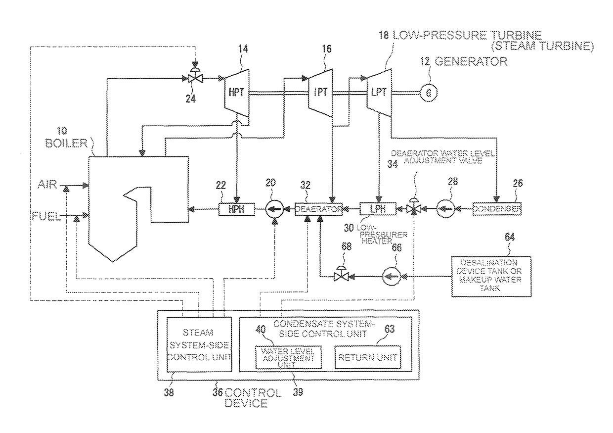
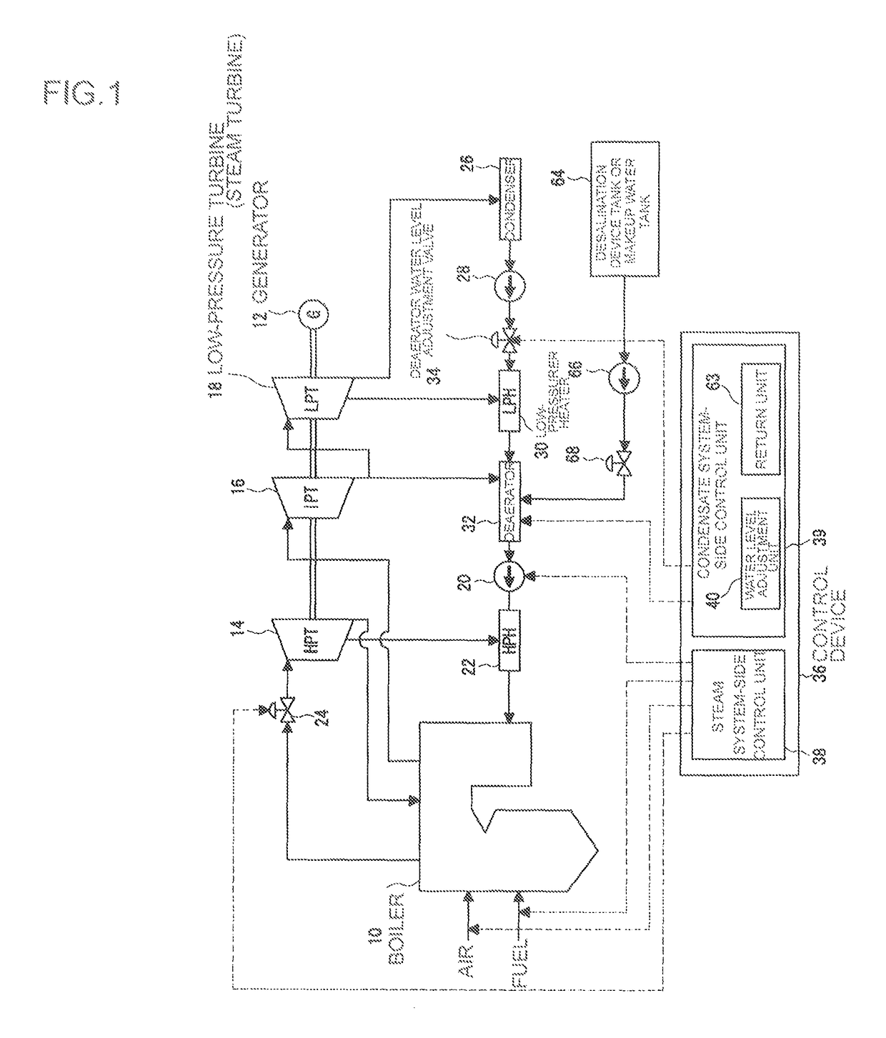
[0083]First, a configuration of a power plant to which an embodiment of the present invention is adapted will be described. FIG. 1 is an overall configuration diagram of a power plant comprising a control device 36 according to a first embodiment of the present invention. A steam system side of the power plant comprises a boiler 10, a high-pressure turbine 14, an intermediate-pressure turbine 16, and a low-pressure turbine 18. In addition, a condensate system side comprises a condenser 26, a low-pressure feed water heater (low-pressure heater) 30, a deaerator 32, and a high-pressure feed water heater 22.

[0084]The boiler 10 heats feed water supplied from the high-pressure feed water heater 22 to generate main steam. The main steam is introduced to the high-pressure turbine 14 via a governor valve 24. The governor valve 24 mainly controls output (power output) of the generator 12.

[0085]Exhaust steam that is discharged by driving the high-pressure turbine 14 is supplied to a reheater i...

second embodiment

[0147]Next, a control device according to a second embodiment of the present invention will be described.

[0148]FIG. 13 is a specific configuration diagram of the control device 36 according to the second embodiment of the present invention, and FIG. 14 is a diagram showing a configuration example of the condensate system-side control unit 39 in the control device 36 according to the second embodiment of the present invention. Moreover, for the second embodiment, only configurations which differ from the first embodiment above will be described.

[0149]In the second embodiment, the condensate system-side control unit 39 calculates a differential value of a frequency fluctuation width or a differential value of a requested load change, and calculates a new setting value of the water level based on the differential value of the frequency fluctuation width or the differential value of the requested load change.

[0150]Specifically, the condensate system-side control unit 39 comprises a diff...

third embodiment

[0163]Next, the control device 36 according to a third embodiment of the present invention will be described.

[0164]FIG. 15 is a specific configuration diagram of the control device 36 according to the third embodiment of the present invention, and FIG. 16 is a diagram showing a configuration example of the condensate system-side control unit 39 in the control device 36 according to the third embodiment of the present invention. Moreover, for the present third embodiment, only configurations which differ from the first and second embodiments above will be described.

[0165]In the third embodiment, a detected value of the water level of the deaerator 32 at a moment of occurrence t0 (refer to FIG. 6) of a frequency fluctuation or a requested load change is inputted to the condensate system-side control unit 39. In addition, when the inputted detected value of the water level is lower than a threshold set in advance, the condensate system-side control unit 39 either disables and does not ...


PUM


Abstract

To provide a condensate flow rate control device and a control method for a power plant which improve responsiveness to frequency fluctuations or requested load changes and can suppress frequency fluctuations with precision or improve precision with which output power conforms to requested load instructions. A power plant to which a condensate flow rate control device is adapted includes a deaerator to which condensate generated by a condenser is supplied via a deaerator water level adjustment valve and into which bleed steam from a steam turbine is introduced. The condensate flow rate control device has a water level adjustment unit for executing condensate flow rate control, wherein the water level adjustment unit adjusts pressure in a condensate flow path extending from the deaerator water level adjustment valve to the deaerator so that inputted frequency fluctuations are suppressed or an output value of a generator conforms to inputted requested load changes.

Description

TECHNICAL FIELD[0001]The present invention relates to a condensate flow rate control device and a condensate flow rate control method for a power plant for controlling a condensate flow rate in accordance with a frequency fluctuation or a requested load change.BACKGROUND ART[0002]Conventionally, power plants are widely used in which a steam turbine generator is driven by steam and converts the steam into power. FIG. 29 is a diagram showing an ordinary thermal power plant. The thermal power plant comprises a boiler 10 which generates steam and a plurality of turbines 14, 16, and 18 which drives a generator 12 using steam from the boiler 10. Feed water is supplied to the boiler 10 from a feed pump 20 via a high-pressure feed water heater 22, and the boiler 10 generates main steam by heating the feed water.[0003]The main steam is supplied to a high-pressure turbine 14 via a governor valve 24. Exhaust steam of the high-pressure turbine 14 is supplied to a reheater inside the boiler 10 a...

Claims


Application Information

Patent Timeline
Patent Type & Authority Patents(United States)
IPC IPC(8): F01K13/02F22D5/26F01K7/44F01K7/22
CPCF22D5/26F01K7/22F01K7/44F01K13/02Y10T137/0374
Inventor INOUE, RIKIOTAKEI, KOICHIDEGUCHI, YUICHIROTSUTSUMI, TAKANORIOHTA, YUJIINOUE, KANTA
Owner MITSUBISHI POWER LTD
Why Eureka
Try Eureka