Device intended to control the angular speed of a train in a timepiece movement and including a magnetic escapement

a technology of angular speed and timepiece movement, applied in the field of magnetic escapements, can solve problems such as limited torque rang

Active Publication Date: 2017-07-25
THE SWATCH GRP RES & DEVELONMENT LTD
View PDF7 Cites 10 Cited by
  • Summary
  • Abstract
  • Description
  • Claims
  • Application Information

AI Technical Summary

Benefits of technology

[0031]each second zone produces per unit of angular length, relative to a first adjacent zone, a stronger repulsion force for the potential magnetic energy accumulation zone or a stronger attraction force for the entry zone and the exit zone;

Problems solved by technology

The problem of anisochronism and also that of the limited useful torque range are due in particular to the fact that a thrust force is applied to the magnet of the resonator over a relatively large radial distance between the positions corresponding to the extrema of its oscillation.

Method used


Image

  • Device intended to control the angular speed of a train in a timepiece movement and including a magnetic escapement
  • Device intended to control the angular speed of a train in a timepiece movement and including a magnetic escapement
  • Device intended to control the angular speed of a train in a timepiece movement and including a magnetic escapement

Examples


third embodiment

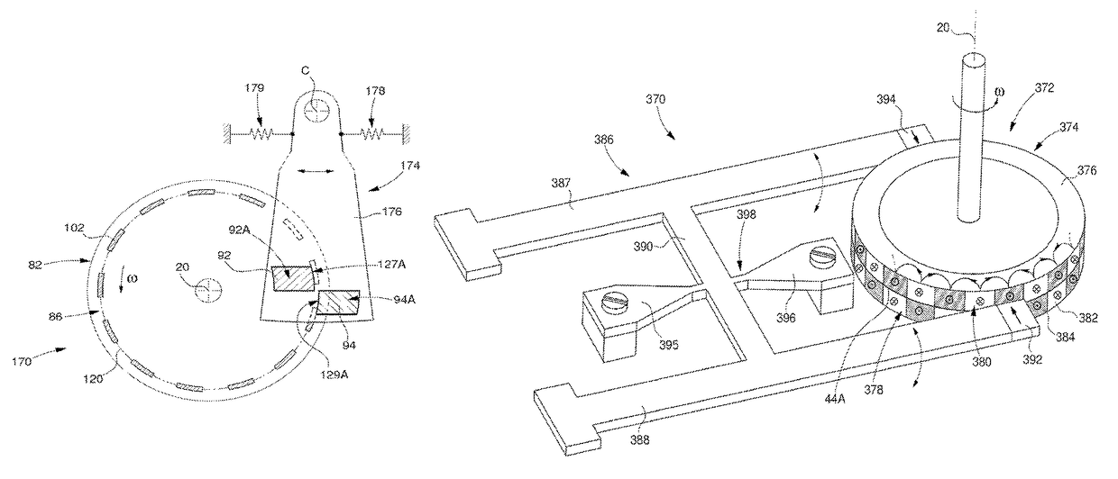
[0123] the regulating device 180 of FIG. 15 comprises a magnetic escapement mobile 182, with two concentric magnetic tracks 86A and 186, and a resonator 184. The first track 86A has already been described and the second track 186 made up of a plurality of magnets 188 is similar thereto, but with a smaller diameter. The potential magnetic energy of the oscillator 180 varies angularly along said second track with the same angular period θP and in a similar way to the variation of the first track. The first and second magnetic tracks have an angular displacement equal to half the angular period. The resonator 184 comprises a coupling element with an active end portion 190 formed by a magnet arranged in repulsion and defining in its general plane a tapered potential magnetic energy accumulation zone 190A. Said portion 190 is arranged in a non-magnetic support 192 fixed to the horological movement by two spring rods 193 and 194 allowing the support 192 to oscillate. The active end portio...

fourth embodiment

[0124] the regulating device 200 of FIG. 16 comprises a magnetic escapement mobile 202 with a radially extended magnetic track 204, as described in the first main embodiment. The magnets 206 of said track are tapered with the two sides parallel in a tangential direction relative to the axis of rotation 20. The oscillator 200 also comprises a resonator 210 of the same type as the one in FIG. 14, said resonator also comprising two coupling elements carried by a balance wheel 212 made of a non-magnetic material, but is distinguished therefrom by the fact that the corresponding two active end portions 46A and 46B are radially narrow relative to the magnets 206 in the rest position of the coupling elements (position shown). The two portions 46A and 46B are situated on both sides of a straight line perpendicular to their longitudinal direction and substantially radial relative to the axis of rotation 20 of the escapement mobile. They both extend relative to said axis over an angular dista...

fifth embodiment

[0125]With reference to FIGS. 17 and 18, the invention will be described below. The regulating device 220 comprises a first magnetic escapement wheel 222 and a second magnetic escapement wheel 224 which are identical and are arranged in the same general plane. Said two escapement wheels form two magnetic structures each defining a radially narrow magnetic track 86A with a plurality of magnets 103. The potential magnetic energy of the oscillator therefore varies angularly in a similar way along said two tracks 86A. The two escapement wheels mesh directly with one another via their respective teeth 226 and 228. The two magnetic tracks are coupled to the same coupling element 234 of the resonator 230 which also comprise a T-shaped non-magnetic support 232 and two spring rods 233A, 233B at the two ends of the transverse bar of said support. The magnet 234 is arranged at the free end of the central bar of the support. The spring rods are arranged such that the magnet 234 can oscillate al...


PUM


Abstract

There is provided a device for regulating the operation of a horological movement, including a magnetic escapement, which includes a resonator and a magnetic escapement mobile turning about an axis. The mobile includes at least one magnetic track with a plurality of magnets having an angular dimension that is greater than their radial dimension. The resonator includes at least one magnetic element for coupling to the magnetic track. The coupling element extends radially relative to the axis of rotation, and has a contour with a portion oriented substantially angularly when the resonator is in the rest position. When the mobile is driven in rotation, each magnet penetrates beneath the coupling element and gradually accumulates some potential magnetic energy. The magnet then exits from beneath the coupling element through the portion and the coupling element receives a pulse located around its rest position.

Description

TECHNICAL FIELD[0001]The present invention relates to the field of devices for regulating the relative angular frequency between a magnetic structure and a resonator which are magnetically coupled so as to define together an oscillator. The regulating device of the present invention times the motion of a mechanical horological movement. More particularly, the invention relates to magnetic escapements for mechanical horological movements in which provision is made for direct magnetic coupling between a resonator and a magnetic structure. Generally, their function is to subject the rotational frequencies of the mobiles of a counter train of this type of horological movement to the resonant frequency of the resonator.[0002]The regulating device therefore comprises a resonator, of which an oscillating portion is provided with at least one magnetic coupling element, and a magnetic escapement arranged so as to control the relative angular frequency between a magnetic structure forming sai...

Claims


Application Information

Patent Timeline
Patent Type & Authority Patents(United States)
IPC IPC(8): G04B15/00G04C5/00G04B17/04G04B17/06G04C3/08G04B15/06
CPCG04C5/005G04B15/00G04B15/06G04B17/04G04C3/08G04B17/06G04B17/32G04B18/00G04C3/107
Inventor DI DOMENICO, GIANNIWINKLER, PASCAL
Owner THE SWATCH GRP RES & DEVELONMENT LTD
Why Eureka
Try Eureka