Airflow modification apparatus and method

a technology of airflow and airflow, which is applied in the field of airflow modification, can solve the problems of inability to achieve the effects of reducing the number of inhaled air, and reducing the spread of airborne pathogens

Active Publication Date: 2017-08-08
WANG RAYMOND R M
View PDF11 Cites 73 Cited by
  • Summary
  • Abstract
  • Description
  • Claims
  • Application Information

AI Technical Summary

Benefits of technology

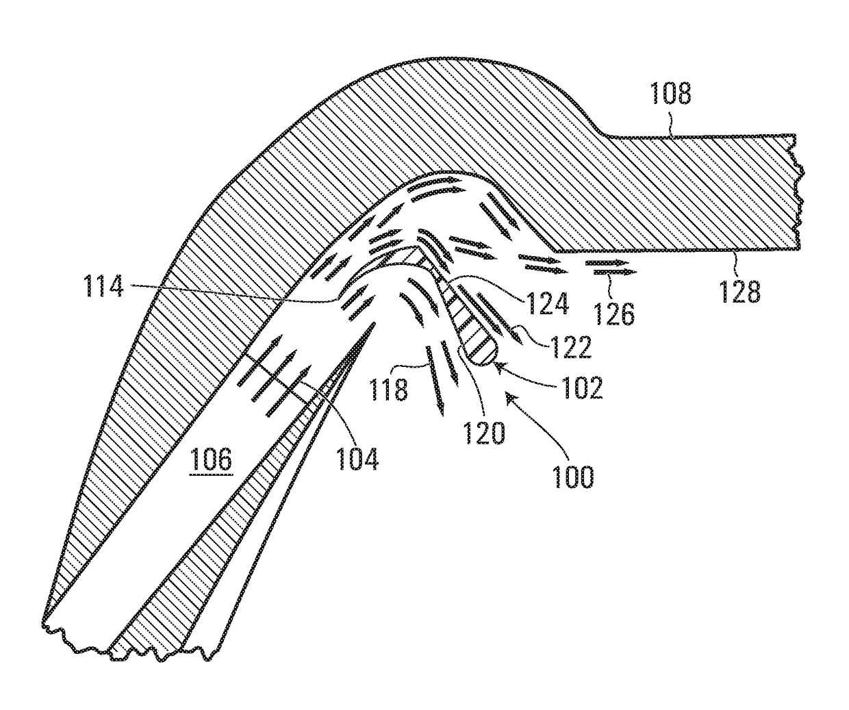
[0013]Advantageously, it has been found that such a redirector tends to significantly reduce airborne pathogen propagation within aircraft cabins. The redirector tends to redirect and stratify downward incoming flows of fresh air, resulting in significantly less mixing of fresh air with exhaled or used air before the airflows exit the cabin through outlets for subsequent conventional pathogen filtration. For example, it has been shown that in one embodiment, the redirector may reduce pathogen inhalation by up to 98%, and may increase the proportion of inhaled air that is fresh air by up to or even over 190% depending on seating position and airplane configuration.

Problems solved by technology

Modern aircraft present a highly vulnerable environment for the transmission of airborne pathogens and disease.
[5] Worsening matters, infected passengers incur widespread societal fear and large socioeconomic costs in providing treatment[6] and conducting contact tracing.
Although some solutions to this problem have been proposed, they have not thus far proven to be viable.
However, this solution does not appear to be economically viable, as it would require a complete overhaul of the aircraft cabin interior, including the removal and replacement of all passenger seats and the installation of appropriate conduits to connect each seat to the aircraft's ventilation system.
Such an extensive overhaul would require the aircraft to be taken out of service for months, resulting in too much lost revenue to permit an airline to adopt such a solution.
This solution also presents ergonomic and aesthetic challenges for passengers, as the fresh air tubing placed in close proximity to the passenger's nose and mouth may hinder passenger comfort, and presents a risk of injury if the aircraft experiences turbulence or if the client moves suddenly after forgetting that an air intake tube is right beside their head.
However, it was concluded that the under-floor displacement air distribution system was not as effective at removing pathogens as a personalized ventilation system.
Moreover, the under-floor displacement air distribution system is also economically unviable, requiring the aircraft to be taken out of service for potentially 1-2 months to install appropriate air ducting.
In addition, inverting the airflow direction in this manner tends to present more unpleasant smells to passengers, such as foot odor and flatulence, for example.
Overhead gasper valves, although perhaps capable of supplying some additional fresh air to passengers, have not generally been effective in reducing pathogen propagation, and are commonly now offered only as an option, rather than a standard feature, to airlines purchasing newly manufactured aircraft.
Although the above discussion focuses on aircraft, other types of public transportation vehicles such as trains and buses for example, or other enclosed spaces, may also suffer from similar pathogen transmission problems.

Method used


Image

  • Airflow modification apparatus and method
  • Airflow modification apparatus and method
  • Airflow modification apparatus and method

Examples


second embodiment

[0136]For example, referring to FIGS. 13 and 14, an apparatus according to the invention is shown generally at 1300. In this embodiment, the apparatus 1300 includes a first redirector 1302, which in turn comprises an elongated protrusion configured to be positioned on the ceiling 128 of the aircraft cabin 108. In this embodiment, the elongated first redirector 1302 extends longitudinally along the ceiling 128 of the cabin 108.

[0137]In this embodiment, the first redirector 1302 has rounded opposing outside and inside sidewalls 1304 and 1306, which extend vertically downward from the ceiling 128 of the cabin 108 while curving inward toward each other until intersecting a horizontal planar bottom surface 1308. Also in this embodiment, in addition to the curved outside and inside sidewalls 1304 and 1306, the forward and aft ends of the first redirector 1302 are also smoothly rounded with no sharp edges. Advantageously, therefore, if a passenger accidentally contacts their head against t...

third embodiment

[0152]Either alternatively or in addition to pivotal adjustment of the entire redirector, in some embodiments the angle between the dividing portion and the redirecting portion may be varied. For example, referring to FIGS. 17A to 17D, a redirector according to the invention is shown generally at 1700. In this embodiment, the redirector 1700 includes a dividing portion 1702 and a redirecting portion shown generally at 1704. More particularly, in this embodiment the redirecting portion 1704 includes a lower redirecting portion 1706 and an upper redirecting portion 1708. The dividing portion 1702 is similar to the dividing portion 110 shown in FIGS. 1-6, except that it includes an additional screwhole 1710 for pivotal attachment to the redirecting portion 1704, or more particularly for pivotal attachment to the lower and upper redirecting portions 1706 and 1708, which have respective screwholes 1712 and 1714 for accommodating the same elongated screw. In this embodiment, the upper red...


PUM


Abstract

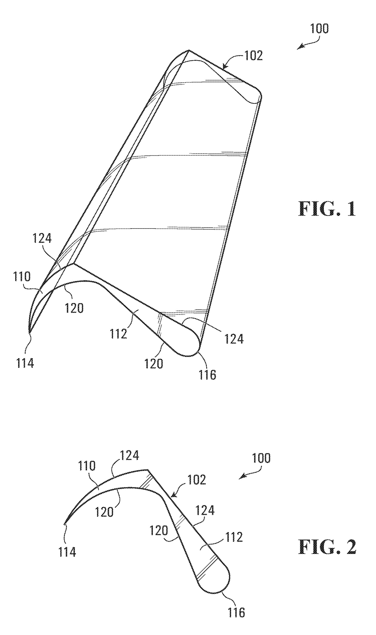
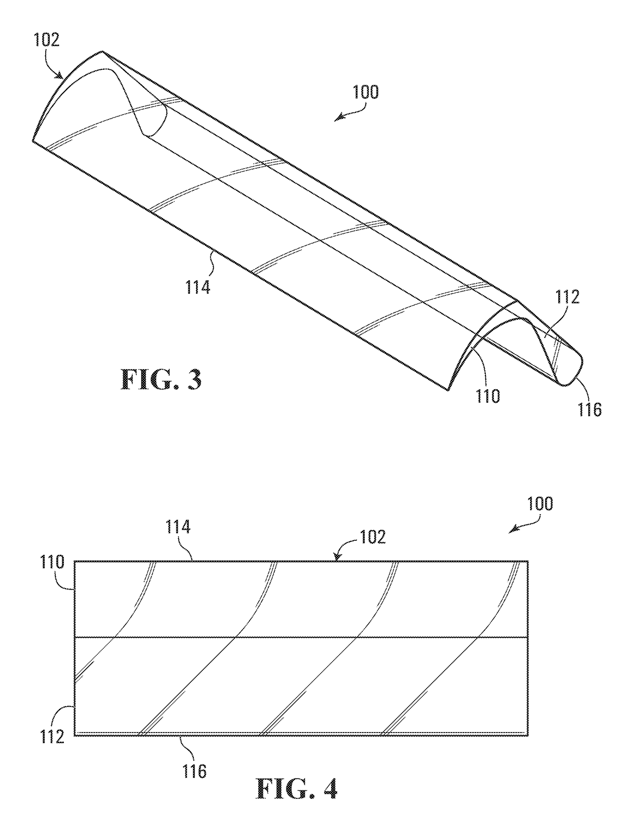
An apparatus for modifying aircraft cabin airflow includes a redirector configured to receive an airflow from an inlet of an aircraft cabin. The redirector is configured to downwardly redirect at least a portion of the airflow. In one embodiment, the redirector includes a dividing portion configured to be oriented generally parallel to the airflow received at the redirector from the cabin inlet, and further includes a redirecting portion configured to be oriented in a generally downward direction. In another embodiment, the redirector includes an elongated protrusion configured to be positioned on a ceiling of the aircraft cabin.

Description

CROSS REFERENCE TO RELATED APPLICATIONS[0001]This application claims the benefit of U.S. Provisional Application No. 62 / 158,889 to Wang, filed May 8, 2015 and entitled “SYSTEM OF AIRCRAFT AIR CONDITIONING MODIFICATIONS TO ENHANCE CABIN AIRFLOW,” which is hereby incorporated by reference in its entirety.BACKGROUND OF THE INVENTION[0002]1. Field of the Invention[0003]The present disclosure relates to airflow modification. More particularly, illustrative embodiments relate to apparatus and methods for modifying aircraft cabin airflow. Other illustrative embodiments may relate to apparatus and methods for modifying airflow in other types of public transportation vehicles such as trains or buses, or in other enclosed spaces such as waiting rooms.[0004]2. Description of the Related Art[0005]Modern aircraft present a highly vulnerable environment for the transmission of airborne pathogens and disease. Particularly in light of recent Influenza and SARS epidemics, the current aircraft cabin ...

Claims


Application Information

Patent Timeline
Patent Type & Authority Patents(United States)
IPC IPC(8): B64D13/00B60H1/34B64D13/06
CPCB64D13/00B60H1/3407B60H1/3414B64D2013/003B64D2013/0651F24F2221/28Y02T50/44Y02T50/56G06F30/15G06F30/23G06F2113/28Y02T50/40Y02T50/50
Inventor WANG, RAYMOND R M
Owner WANG RAYMOND R M
Why Eureka
Try Eureka