
Write buffering

a buffering and data technology, applied in the field of data management in a storage system, can solve the problems of system caching performance, failure to recognize possible improvements brought about by the solid-state drive architecture, and the storage system caching performance decline, so as to maximize concurrent data transfer operations, maximize parallel operations, and increase performance

Active Publication Date: 2017-08-15
BITMICRO LLC
View PDF316 Cites 4 Cited by
  • Summary
  • Abstract
  • Description
  • Claims
  • Application Information

AI Technical Summary

Benefits of technology

The present invention describes a method for managing bandwidth in a storage device with both volatile and non-volatile caches. By optimizing data transfer operations and distributing striping across rotational drives, the invention achieves better performance compared to conventional methods. The use of specific algorithms and a cache state-based algorithm allows for efficient data flow and further improvements in performance. In summary, the invention enhances the performance of hybrid storage devices by maximizing data transfer operations and optimizing data flow.

Problems solved by technology

In such systems, the management of the drive cache is done by the host and the overhead brought about by this contributes to degradation of the caching performance of the storage system.
However, prior solutions that made use of non-volatile memory as cache did not take advantage of the architecture of the non-volatile memories that could have further increased the caching performance of the system.
The storage system does not make any distinction between a rotational drive and a solid-state drive cache thus failing to recognize possible improvements that can be brought about by the architecture of the solid-state drive.

Method used


Image

  • Write buffering
  • Write buffering
  • Write buffering

Examples


Embodiment Construction

[0044]Cache line is an unit of cache memory identified by a unique tag. A cache line consists of a number of host logical blocks identified by host logical block addresses (LBAs). Host LBA is the address of a unit of storage as seen by the host system. The size of a host logical block unit depends on the configuration set by the host. The most common size of a host logical block unit is 512 bytes, in which case the host sees storage in units of 512 bytes. The Cache Line Index is the sequential index of the cache line to which a specific LBA is mapped.

[0045]HDD LBA (Hard-Disk Drive LBA) is the address of a unit of storage as seen by the hard disk. In a system with a single drive, there is a one-to-one correspondence between the host LBA and the HDD LBA. In the case of multiple drives, host LBAs are usually distributed across the hard drives to take advantage of concurrent IO operations.

[0046]HDD Stripe is the unit of storage by which data are segmented across the hard drives. For exa...


PUM


Abstract

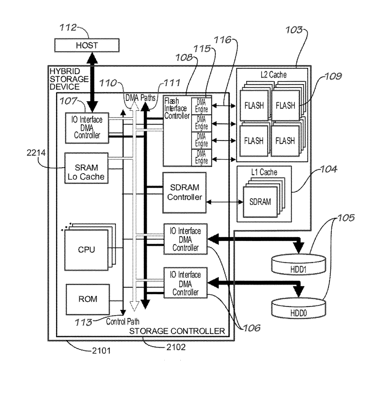
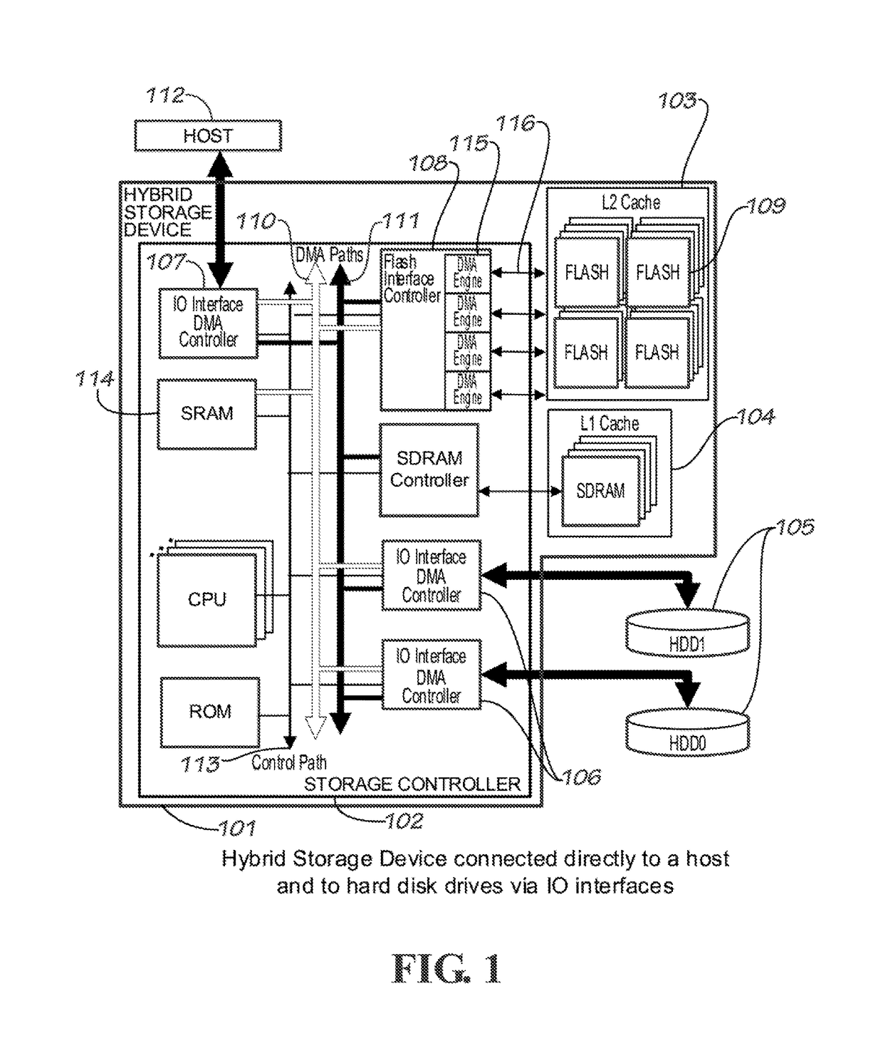
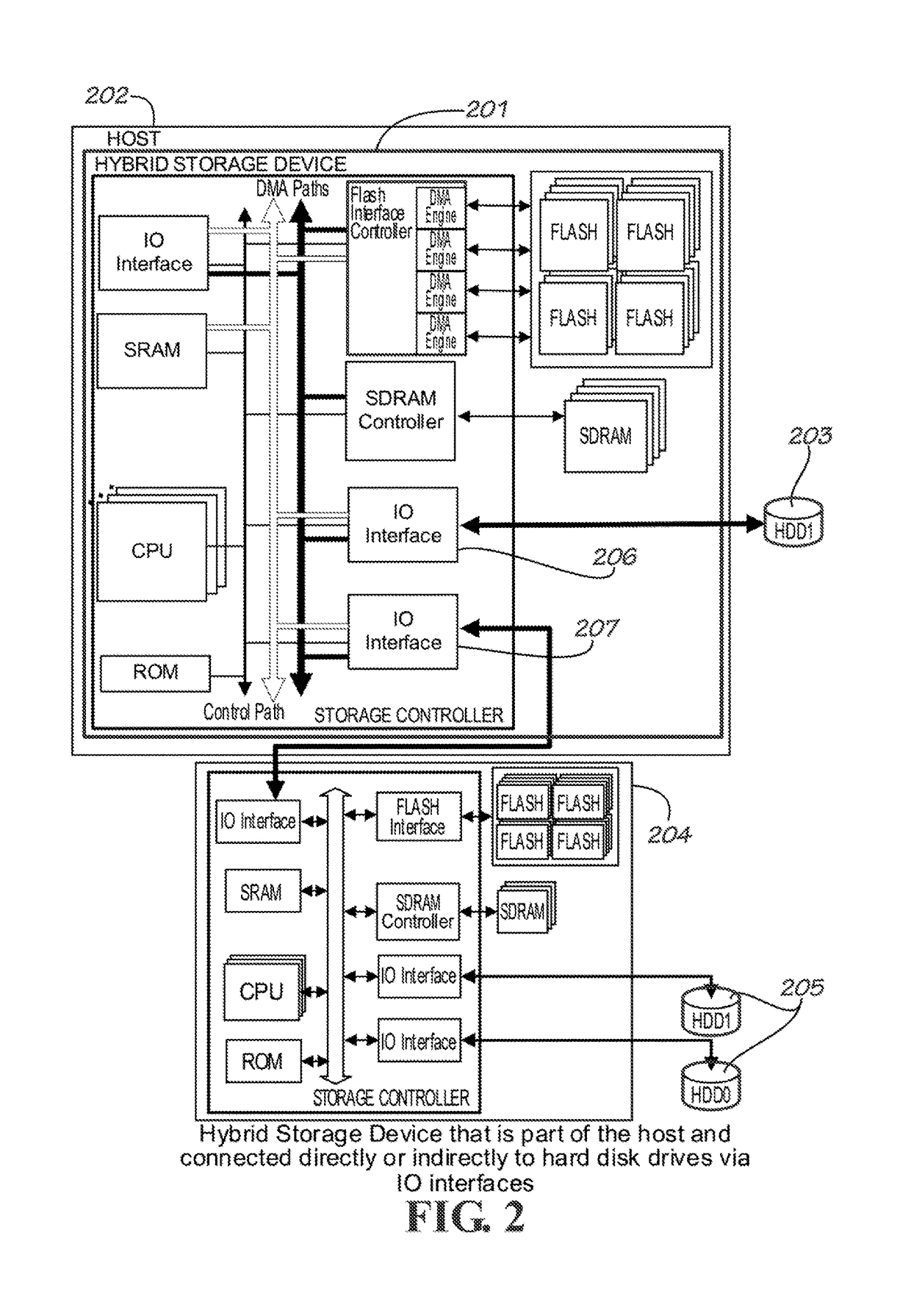
A hybrid storage system is described having a mixture of different types of storage devices comprising rotational drives, flash devices, SDRAM, and SRAM. The rotational drives are used as the main storage, providing lowest cost per unit of storage memory. Flash memory is used as a higher-level cache for rotational drives. Methods for managing multiple levels of cache for this storage system is provided having a very fast Level 1 cache which consists of volatile memory (SRAM or SDRAM), and a non-volatile Level 2 cache using an array of flash devices. It describes a method of distributing the data across the rotational drives to make caching more efficient. It also describes efficient techniques for flushing data from L1 cache and L2 cache to the rotational drives, taking advantage of concurrent flash devices operations, concurrent rotational drive operations, and maximizing sequential access types in the rotational drives rather than random accesses which are relatively slower. Methods provided here may be extended for systems that have more than two cache levels.

Description

[0001]This application claims the benefit of and priority to U.S. Provisional Application 61 / 980,561 filed 16 Apr. 2014. This U.S. Provisional Application 61 / 980,561 is hereby fully incorporated herein by reference.[0002]This application is a continuation-in-part of U.S. application Ser. No. 14 / 217,436, “Multi-Leveled Cache Management In A Hybrid Storage System”, filed 17 Mar. 2014, which claims the benefit of and priority to U.S. Provisional Application 61 / 801,422, filed 15 Mar. 2013. U.S. application Ser. No. 14 / 217,436 and U.S. Provisional Application 61 / 801,422 are each hereby fully incorporated herein by reference.BACKGROUND[0003]Field[0004]This invention relates to the management of data in a storage system having both volatile and non-volatile caches. It relates more specifically to the methods and algorithms used in managing multiple levels of caches for improving the performance of storage systems that make use of Flash devices as higher-level cache.[0005]Description of Rel...

Claims


Application Information

Patent Timeline
IPC IPC(8): G06F12/0831G06F12/0875
CPCG06F12/0833G06F12/0875G06F2212/62G06F2212/452G06F12/0804G06F12/0811G06F12/0844G06F12/0868G06F11/1076G06F2212/1016G06F2212/217G06F2212/225G06F2212/313Y02D10/00
Inventor BRUCE, ROLANDO H.DELA CRUZ, ELMER PAULEARCEDERA, MARK IAN ALCID
Owner BITMICRO LLC
Learn More