Quantitative X-ray analysis—multi optical path instrument

a multi-oscillator and optical path technology, applied in the field of quantitative xray analysis and apparatus, can solve the problems of not providing enough energy resolution, affecting the accuracy of measurement of a large number of components in a sample, and consuming a considerable amount of resources in maintaining the temperature above the melting temperature, so as to achieve the effect of reducing the overall measurement time, improving the accuracy of measurement, and shortening the measurement tim

Active Publication Date: 2017-08-22
PANALYTICAL BV
View PDF15 Cites 7 Cited by
  • Summary
  • Abstract
  • Description
  • Claims
  • Application Information

AI Technical Summary

Benefits of technology

[0014]wherein the elements are divided between the first and second subsets according to a criterion to deliver a reduced overall measurement time to measure all the plurality of elements to a given accuracy and / or precision compared to using only one of the energy dispersive XRF and the wavelength dispersive XRF.
[0054]The collimator may be a variable collimator with a plurality of settings, with at least one setting for reducing the intensity of X-ray radiation reaching the energy dispersive X-ray detector and at least one setting for reducing the detected spot size on the sample.

Problems solved by technology

However, for high accuracy, especially where the emission lines of different elements are close in energy and even overlapping, this approach may not provide enough energy resolution.
However, in general, it may be said that accurately measuring a large number of components in a sample may take a considerable time, especially where some of the components are trace components present in small quantities.
This can cost a considerable amount of resource in maintaining the temperature above the melting temperature.
However, such equipment is not suitable in cost-sensitive applications since there is a need for a large number of X-ray components.
For low atomic number its sensitivity is poor compared to WDS.
For the high energy of high atomic number elements the efficiency of the detector is low for thin Si body detectors (˜500 um), the X-rays may pass through the detector with little interaction, so energy dispersive XRF may also be unsuitable at very high energies.

Method used


Image

  • Quantitative X-ray analysis—multi optical path instrument
  • Quantitative X-ray analysis—multi optical path instrument
  • Quantitative X-ray analysis—multi optical path instrument

Examples


Embodiment Construction

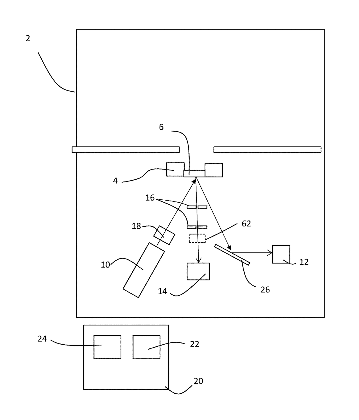
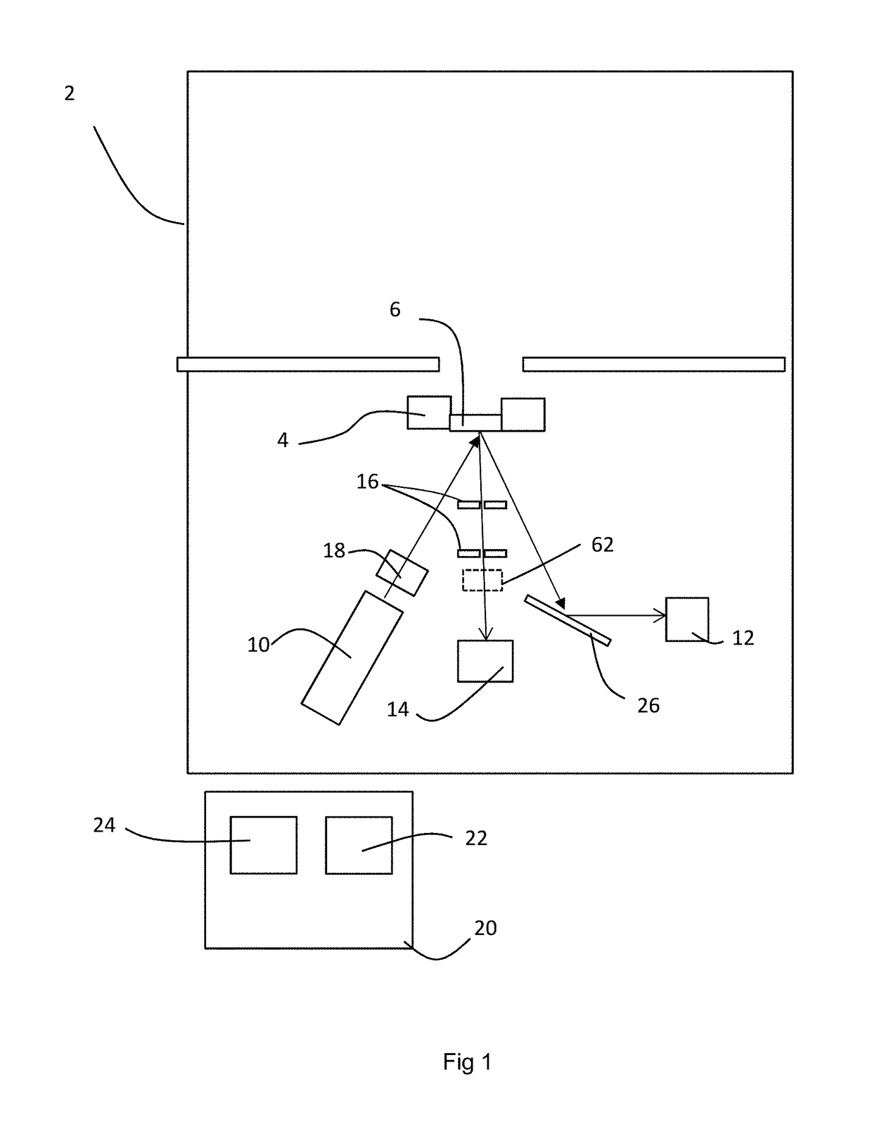
[0061]The invention relates to a method and apparatus for determining the elemental composition of a sample with multiple elements relatively quickly.

[0062]An X-ray apparatus 2 has a sample stage 4 for holding a sample 6. The upper part of the apparatus 2 is used for sample loading.

[0063]In practice, this apparatus 2 is a conventional XRF apparatus with an X-ray source 10 is mounted below the sample stage 4. In this embodiment there is a wavelength dispersive X-ray detector 12 for measuring X-ray fluorescence below the sample stage 4. The wavelength dispersive X-ray detector has an analyser crystal 26 for selecting X-rays only of a particular wavelength and an X-ray detector. The analyser crystal 26 and wavelength dispersive X-ray detector 12 are movable to allow selection of different wavelengths. Typically, the analyser crystal may be made of LiF, for example.

[0064]Additionally, an energy dispersive X-ray detector 14 is also mounted below the sample stage 4 to measure an X-ray spe...


PUM

PropertyMeasurementUnit
poweraaaaaaaaaa
poweraaaaaaaaaa
currentaaaaaaaaaa

Abstract

Apparatus includes an X-ray source 10, a wavelength dispersive X-ray detector for measuring X-ray fluorescence (XRF) and an energy dispersive X-ray detector 14 again for measuring X-ray fluorescence. Selected elements are measured using the wavelength dispersive process to reduce the overall measurement time compared with using only one of the two detectors or compared to a simple approach of measuring low atomic number elements with the wavelength dispersive detector and high atomic number elements with the energy dispersive detector. The selection can take place dynamically, in particular on the basis of the results of the energy-dispersive detector.

Description

CROSS-REFERENCE TO RELATED APPLICATIONS[0001]This application is based on and claims priority to U.S. Provisional Patent Application Ser. No. 62 / 127,591, filed on Mar. 3, 2015, which is hereby incorporated by reference as if set forth in its entirety herein.FIELD OF INVENTION[0002]The invention relates to a method of quantitative X-ray analysis and apparatus for carrying out the method.BACKGROUND TO THE INVENTION[0003]Materials analysis using X-rays provides accurate data in a number of applications and industries. X-ray fluorescence (XRF) measurements allow the determination of the elemental composition of a sample. This may be carried out in dedicated X-ray fluorescence apparatus with an X-ray source, an X-ray detector and a sample stage for holding a sample.[0004]In order to make an XRF measurement it is necessary to measure the intensity of X-rays at a particular wavelength, equivalently energy, excited in a sample by the incident X-ray beam. In the case of energy dispersive XRF...

Claims


Application Information

Patent Timeline
Patent Type & Authority Patents(United States)
IPC IPC(8): G01N23/22G01N23/223
CPCG01N23/223
Inventor HEGEMAN, PETRONELLA EMERENTIANABRONS, GUSTAAF CHRISTIANKOMELKOV, ALEKSANDRVREBOS, BRUNO A. R.VAN DEN HOOGENHOF, WALTHERUSZARKADAS, CHARALAMPOS
Owner PANALYTICAL BV
Why Eureka
Try Eureka