Trapped vortex particle-to-vapor converter

a vortex particle and converter technology, applied in the field of particle analysis apparatus and methods, can solve the problems of not being able to successfully aspirate under the conditions described, sensor not capturing particles, and particle not being sampled, etc., to achieve small or negligible pressure drop, convenient operation, and low flow resistance

Inactive Publication Date: 2017-08-29
ENERTECHNIX
View PDF21 Cites 10 Cited by
  • Summary
  • Abstract
  • Description
  • Claims
  • Application Information

AI Technical Summary

Benefits of technology

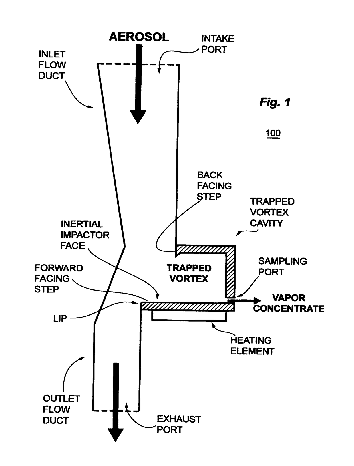
[0025]The inlet flow duct and trapped vortex apparatus has very little flow resistance, as compared to a filter element or SPME bed, resulting in a small or negligible pressure drop, and thus can be conveniently operated at the high throughput flow rates needed to sample at an inspection station such as a whole body portal or a luggage conveyor belt, for example with minimal power requirements.
[0026]While permitting high intake flow velocities, the apparatus solves a significant issue: the flow mismatch in volumetric flow rate between the intake stream of ambient gas and the need for a sampling flow rate to an analytical module that is two or more orders of magnitude smaller (without loss of target analyte).
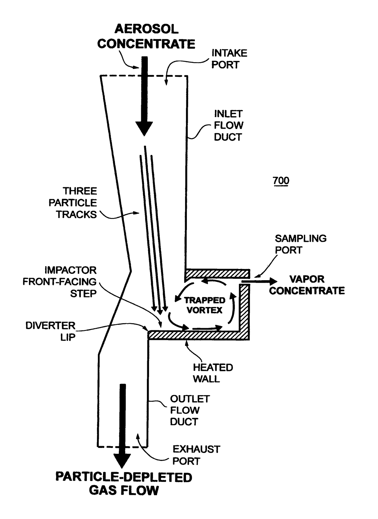
[0027]The backward facing step of the cavity induces flow separation around the diverter lip and a formation of a strongly isolated recirculation zone (trapped vortex) in the trap cavity. The vortex is very stable, i.e., the cavity does not allow significant vortex shedding, trapping most of the material (and heat) inside the cavity.
[0028]Surprisingly, there is an insignificant retrograde leakage of vortex contents into the bulk flow, ensuring that target analyte is not lost. This in part is related to the formation of a boundary layer between the trapped vortex and the inlet gas stream, but also arises from the steady mass flow out of the vortex cavity as needed for sampling. Heat does not escape the trap for the same reason, minimizing the overall energy requirements of the system.

Problems solved by technology

In particular, the recent increased threat to society from explosive devices and illicit drug traffic has lead to the development of sensitive systems for the detection of vapors and particles from explosives and drugs.
Detectors of this class cannot tolerate humid air.
Unfortunately the silicone membrane allows only a small part of the analyte vapors into the detector.
Furthermore, the sensor does not capture particles, which can pass through the system without being detected.
However, particles are not sampled and would not be successfully aspirated under the conditions described, which relies on a 250 Watt lamp and a spring-actuated plunger for generating a puff of air.
U.S. Pat. No. 4,092,218 to Fine also discloses a method for the selective detection of explosives vapors, but does not show that it is capable of sampling particles.
While it is tempting to limit collection to vapors alone, it is known that vapors of interest are frequently associated with or released from particles on heating, thus systems that collect only vapors may miss critical evidence.
However, the process is inherently slow because each article or person must be moved into the box or chamber and the box sealed before sampling, an obvious disadvantage when large numbers of articles or persons must be screened, or when the articles are larger than can be reasonably enclosed, such as a truck, shipping container, or the hallway surfaces of a building.
Unfortunately, continuous operation tends to clog the filter and reduces the filter temperature.
Some vapors may also stick to the screen, however, the surface chosen for particle collection is not in general optimal for vapor collection.
These systems operate in batch mode, resulting in interruption of sampling during processing Implementation has further proved difficult because particles have been found to poison commonly used vapor trap materials and means for efficiently separating particles from vapors are not recognized.
Also an unsolved problem is the elimination of vapor and gaseous interferences, such as water vapor, exogenous nitrous oxides, vehicle exhausts, sulfates, solvent vapors, and so forth, which are present in air and are known to interfere with or complicate a variety of analytical protocols.
Thus direct collection of vapors is associated with both interferences and with loss of the particle signal, whereas combined collection can poison the vapor adsorbate.

Method used


Image

  • Trapped vortex particle-to-vapor converter
  • Trapped vortex particle-to-vapor converter
  • Trapped vortex particle-to-vapor converter

Examples


Embodiment Construction

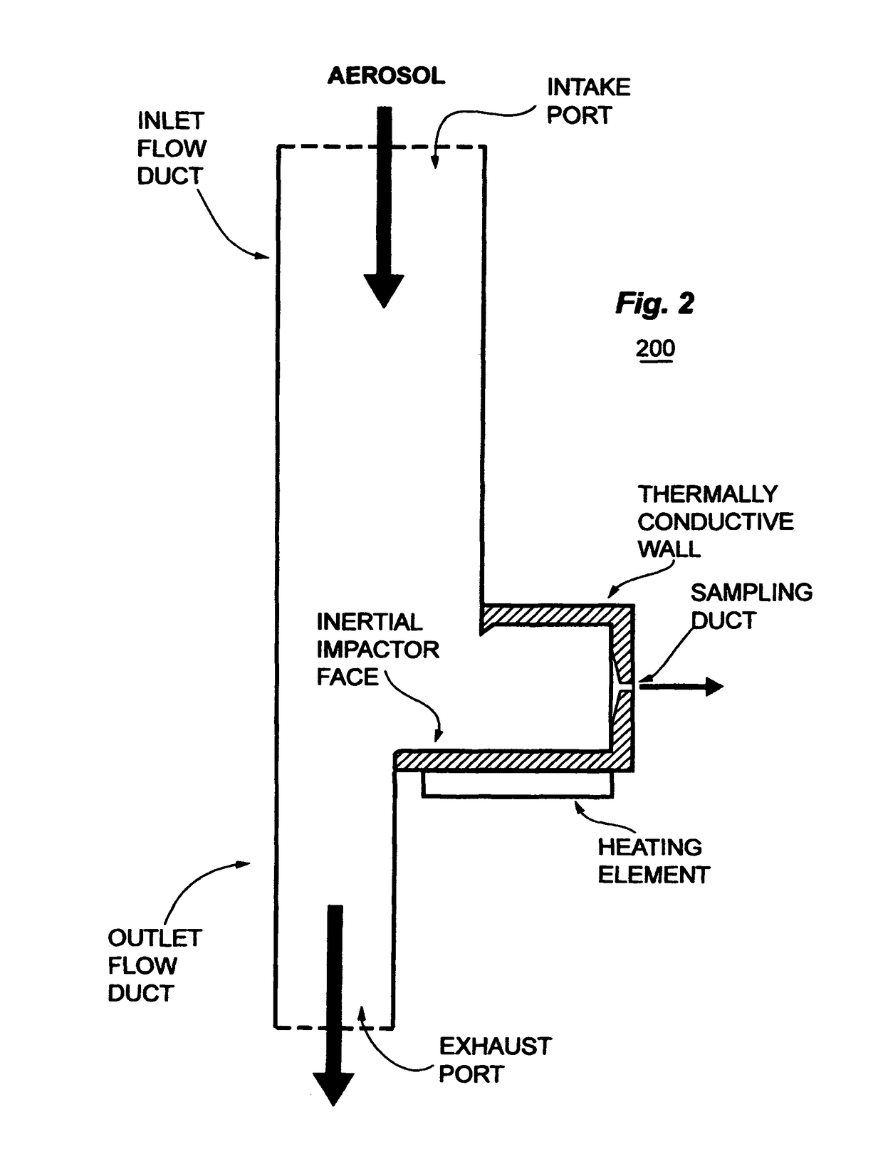
[0052]Referring to the figures, wherein like reference numerals refer to like components in the various views, there is illustrated a trapped vortex apparatus for vapor concentration and sampling, wherein selected embodiments are generally denominated 100, 200, 700, 1300 or 1400 herein.

[0053]An effective screening system for threat compounds such as explosives (as well as chemical hazards and illicit substances) must be able to collect, concentrate, and analyze trace samples quickly and accurately. Analysis is improved by selectively separating particles from a carrier gas stream in a trapped vortex or on an impactor surface within a trapped vortex cavity, and then heating the particles to strip off any volatile constituents for analysis in a small resident volume of gas trapped in a stable cyclonic eddy or vortex.

[0054]FIG. 1 is a schematic view of a first embodiment 100 of an aerosol impactor with trapped vortex solid-to-vapor concentrator.

[0055]An intake port forms the mouth of a...


PUM

PropertyMeasurementUnit
flow rateaaaaaaaaaa
flow rateaaaaaaaaaa
volumeaaaaaaaaaa

Abstract

Apparatus and methods for selectively separating a volatile constituent of a particle from a gas stream for analysis. Particles are separated from bulk flow by inertia and impacted in a cavity containing a small but stable vortex or eddy. Heat is applied to volatilize constituents of the particles. The gas entrained within the vortex, which exchanges only slowly with the bulk flow, is withdrawn for analysis. In this way, a high volume flow containing particles of interest is reduced to a low volume flow containing a vapor concentrate. Advantageously, the apparatus may be operated at very low pressure drops in fully continuous, semi-continuous or batch mode according to the requirements of the downstream analytical unit. The apparatus finds use in active surveillance, such as in use of aerosols to detect explosives or chemical residues on persons, vehicles or luggage in real time.

Description

[0001]This application relates to U.S. Provisional Application Ser. No. 61 / 621,220 filed 6 Apr. 2012 and entitled “Trapped Vortex Solid-to-Vapor Concentrator”FIELD OF THE INVENTION[0002]This invention is related to particle analysis apparatus and methods, where a trapped vortex cavity operatively conjoined to a gas flow channel, the trapped vortex cavity having an inertial impactor surface impinging on the gas flow. The trapped vortex cavity is heated so that particles entering the trapped vortex by inertia are stripped of volatiles. A vapor concentrate is withdrawn from the cavity for analysis of particle-associated volatile constituents.BACKGROUND[0003]There is a need for inspection and sampling of persons, articles of clothing, buildings, furnishings, vehicles, baggage, cargo containers, dumpsters, packages, mail, and the like for contaminating residues (termed here more generally “trace analytes” or “target analytes”) that may indicate chemical hazards, explosives hazards, or il...

Claims


Application Information

Patent Timeline
Patent Type & Authority Patents(United States)
IPC IPC(8): B01D49/00B01D45/12B01D45/08B01D50/00B01D45/16
CPCB01D45/16B01D45/08B01D45/12B01D50/002B01D50/20
Inventor NOVOSSELOV, IGORARIESSOHN, PETER
Owner ENERTECHNIX
Why Eureka
Try Eureka