
Gas distributor, and method of forming the same

a distributor and gas technology, applied in the direction of combustion types, lighting and heating apparatus, coatings, etc., can solve the problems of difficult to change the shape of the flow path, complicated and expensive forming process, turbulence between the bordering surfaces, etc., and achieve the effect of improving process accuracy and being easy to form

Active Publication Date: 2017-08-29
DONGWON PRECISION MACHINERY
View PDF8 Cites 6 Cited by
  • Summary
  • Abstract
  • Description
  • Claims
  • Application Information

AI Technical Summary

Benefits of technology

The present invention provides a gas distributor for a CVD process that can improve process accuracy by guiding the flow of discharged gas. Additionally, the gas distributor allows for the easy designing of the flow paths for discharging process gases and is particularly useful in forming a uniform film. The nozzle member, gas distributor, and method of forming the gas distributor of the present invention have a unique design to enable the shape of the flow paths to be freely designed, easily formed, and assembled in parallel with each other.

Problems solved by technology

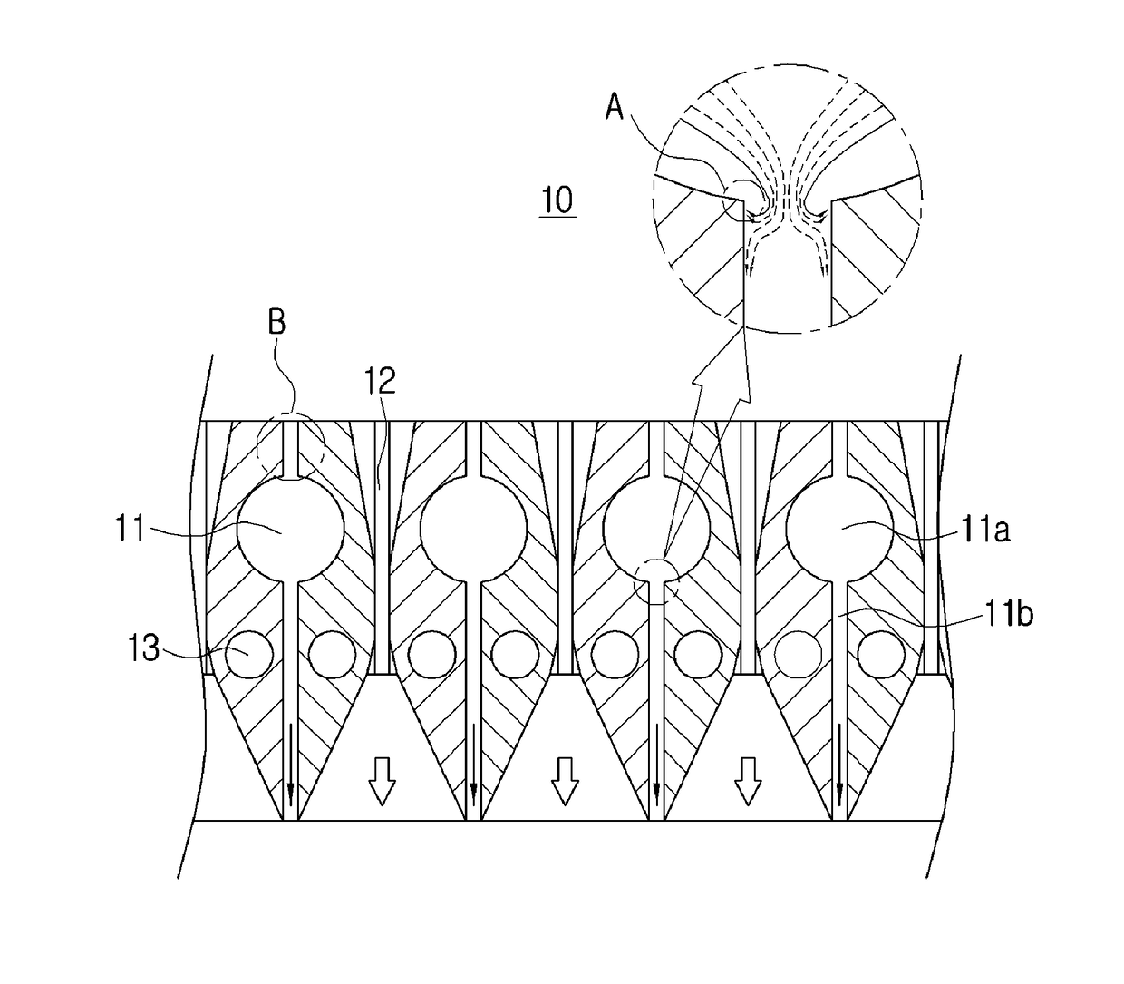
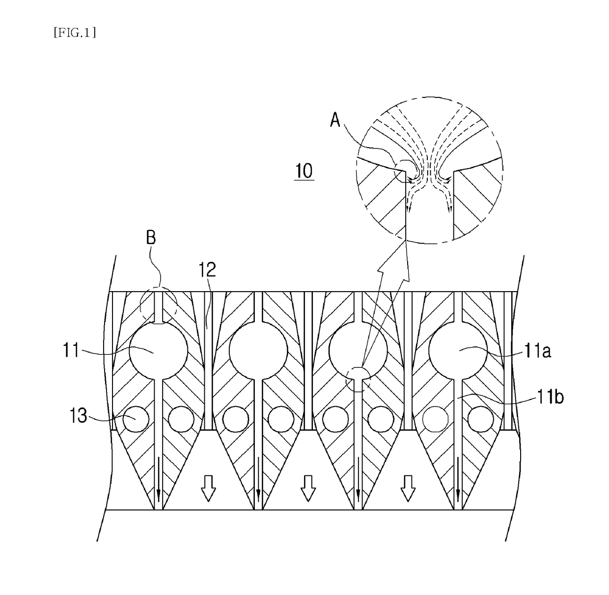
Accordingly, the gas distributor to feed different kinds of process gases is manufactured through various forming processes such as the previously mentioned gun drilling, wire electric discharge machining, and electric discharge machining, considering the positions, shapes, and sizes of the flow paths that will be formed in the plate of a predetermined thickness, which makes a forming process both complicated and expensive.
In addition, forming the flow paths in the plate is limited in terms of the range of forming, and particularly, gun drilling, electric discharge machining, and wire electric discharge machining can form only holes and gaps of linear shapes, and thus, even when the shapes of the flow paths require changing in consideration of gas flow, the limitation of forming makes it difficult to change the shapes of the flow paths.
In this case, when two flow paths meet, bordering surfaces are orthogonal to each other, which causes turbulences between the bordering surfaces.
Furthermore, even when the shapes of the flow paths require changing so as to change flow rate, pressure and velocity which are important factors in controlling the process gases flowing through the flow paths, the forming process mentioned above can change only shapes of holes, thereby causing problems due to the limitation in controlling the process gases.
Next, forming by means of wire electric discharge machining is performed by penetrating the plate based upon the characteristics of forming thereof, thereby often causing undesired results.
However, such an undesired hole may cause the first gas flow path and the second gas flow path to interrupt gas flow due to by-products produced by the flow of two process gases since the first gas flow path and the second gas flow path communicate with each other.

Method used


Image

  • Gas distributor, and method of forming the same
  • Gas distributor, and method of forming the same
  • Gas distributor, and method of forming the same

Examples


Embodiment Construction

[0063]Hereinafter, exemplary embodiments of the present invention will be described in detail with reference to the accompanying drawings. Throughout the drawings, the same reference numerals will refer to the same or like parts. Specific structural and functional descriptions of embodiments of the present invention disclosed herein are only for illustrative purposes of the embodiments of the present invention. The present invention may be embodied in many different forms without departing from the spirit and significant characteristics of the present invention. Therefore, the embodiments of the present invention are disclosed only for illustrative purposes and should not be construed as limiting the present invention.

[0064]Meanwhile, it will be understood that, although the terms “first”, “second”, etc. may be used herein to describe various elements, these elements should not be limited by these terms. These terms are only used to distinguish one element from another element. For ...


PUM

PropertyMeasurementUnit
Diameteraaaaaaaaaa
Widthaaaaaaaaaa
Circumferenceaaaaaaaaaa

Abstract

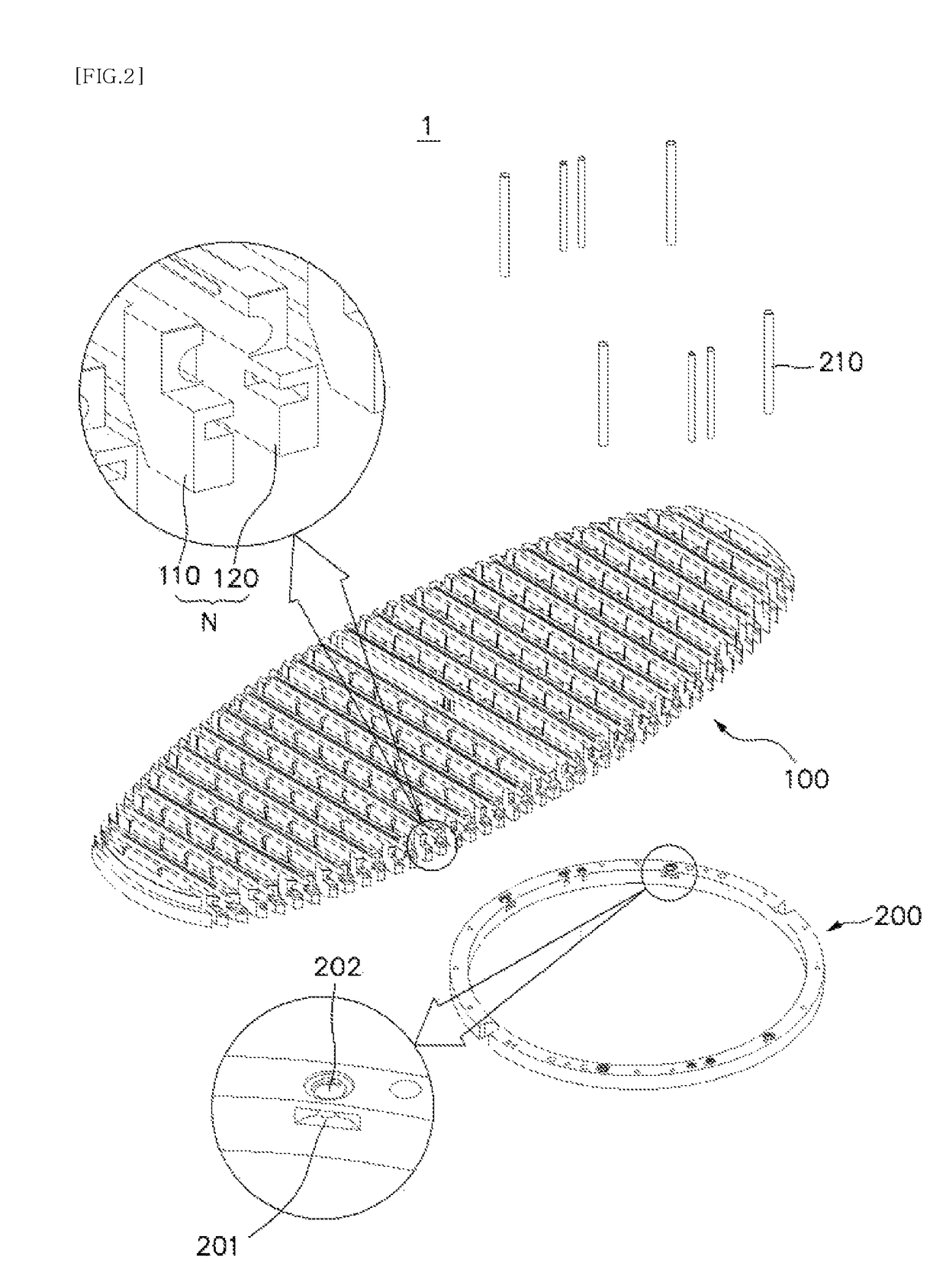
Disclosed is a gas distributor, including: a nozzle unit formed by joining a pair of nozzle members together such that the nozzle members face each other with a first nozzle gap defined between the nozzle members; and a nozzle assembly in which at least two nozzle units are assembled together in parallel, in which the nozzle gap includes a first flow path formed in parallel in a direction of the nozzle member, and a second flow path extended from the first flow path, formed with a smaller width than a width of the first flow path along a bonded surface, and discharging gas through an end portion of one side of the second flow path, and the second flow path is extended with the first flow path, and is inclinedly provided so that a width is gradually decreased in a portion adjacent to the first flow path.

Description

BACKGROUND OF THE INVENTION[0001]Field of the Invention[0002]The present invention relates to a gas distributor used in a manufacturing process of a semiconductor device or a liquid crystal display device.[0003]Description of the Related Art[0004]Generally, a semiconductor device or a Liquid Crystal Display (LCD) is manufactured by depositing a film by depositing gas and the like on a wafer or glass which is a substrate. For example, the semiconductor device and the LCD is manufactured by repeatedly performing a process of forming a film by depositing gas on a substrate, and a lithography process, an etching process, and an ion implantation process for forming a desired pattern. In this case, the process of forming the film includes Chemical Vapor Deposition (CVD), metal deposition, and the like, and particularly, in the process of the CVD, a source gas for depositing is distributed on a substrate loaded in a chamber, and thus a fine and thin film is formed on the substrate. In this...

Claims


Application Information

Patent Timeline
IPC IPC(8): C23C16/455B05B17/04B05B1/04B05B1/14B05B7/04B05B9/04B05B7/06H01L21/67F23D14/78
CPCC23C16/45563H01L21/67017B05B17/04B05B1/04F23D14/78B05B1/042B05B7/04B05B9/0403B05B1/044B05B7/06B05B1/14C23C16/45572C23C16/45574C23C16/45582C23C16/45585H01L21/00C23C16/45565H01L21/02312H01L21/0262H01L21/205
Inventor CHO, DUK HYUNG
Owner DONGWON PRECISION MACHINERY
Learn More