Hydrogen storage tank comprising metal hydrides produced through simplified manufacture and storage device comprising at least such a tank

a technology of metal hydrides and storage tanks, which is applied in the direction of vessel manufacturing, packaging, pressure vessels, etc., can solve the problems of safety problems, still uncommon, and hydrogen fuel cells, and achieve the effect of convenient assembly and effective sealing

Inactive Publication Date: 2017-08-29
COMMISSARIAT A LENERGIE ATOMIQUE ET AUX ENERGIES ALTERNATIVES
View PDF21 Cites 3 Cited by
  • Summary
  • Abstract
  • Description
  • Claims
  • Application Information

AI Technical Summary

Benefits of technology

[0030]Consequently, an aim of the present invention is to offer a hydrogen storage device of simple and robust design offering effective confinement of the hydrogen storage material.
[0032]Hence, each cup delimits with the one immediately above it in a simple and lasting manner a sealed compartment for the storage material. Indeed, employing an at least partially elastic connection makes it possible to avoid a hyperstatic structure and therefore guarantee effective sealing both between the longitudinal hydrogen supply and collection duct and the central portion of the cups and at the outer periphery of the cups. Moreover, the latter is more capable of withstanding the stresses due to the thermal expansions.
[0033]The assembly is in addition very simple, since it is performed by simple mutual engagement; no welding or complex means of assembly is used. The tank can then be easily assembled in a glove box.

Problems solved by technology

Hydrogen fuel cells are already used in certain applications, in motor vehicles for example, but are still uncommon, particularly owing to the precautions to be taken and the difficulties in storing hydrogen.
Hydrogen can be stored in compressed form at between 350 and 700 bars, which raises safety problems.
Provision must be made in this case for tanks capable of withstanding these pressures, in the knowledge however that these tanks, when mounted on vehicles, may be subject to impacts.
It may be stored in liquid form; yet this storage only provides limited storage performance and does not allow storage over long periods.
Tanks containing hydrogen in liquid form are generally not very resistant to mechanical impacts, which raises significant safety issues.
Indeed, decrepitation causes emergence of increasingly fine powders that migrate by gravity towards the floor of the tank through the network of particles.
Furthermore, the bed of powder tends to retract, i.e. undergo a reduction in its volume during a desorption process, leaving an empty space between the walls of the tank and the bed of the hydrogen storage material.
In particular, the level of the bed of powder in the tank is not that achieved during the preceding absorption.
The powder is thus no longer able to escape from its compartment and accumulate in an area below.
Firstly, this device is highly rigid and may be weakened in case of thermal expansion
Secondly, it poses difficulties in filling and in its installation, particularly when assembled and filled in a glove box.
In addition, it cannot be easily dismantled.

Method used


Image

  • Hydrogen storage tank comprising metal hydrides produced through simplified manufacture and storage device comprising at least such a tank
  • Hydrogen storage tank comprising metal hydrides produced through simplified manufacture and storage device comprising at least such a tank
  • Hydrogen storage tank comprising metal hydrides produced through simplified manufacture and storage device comprising at least such a tank

Examples


Embodiment Construction

[0071]Metal hydrides will be denoted by “storage material” in the further description.

[0072]In the description that follows, the tank(s) described above display a circular cylindrical shape, which represents the preferred embodiment.

[0073]Nevertheless, any tank formed by a hollow element having a longitudinal dimension greater than its crossways dimension and possessing a section of any kind, for example circular or polygonal or elliptical, does not go outside the scope of the present invention.

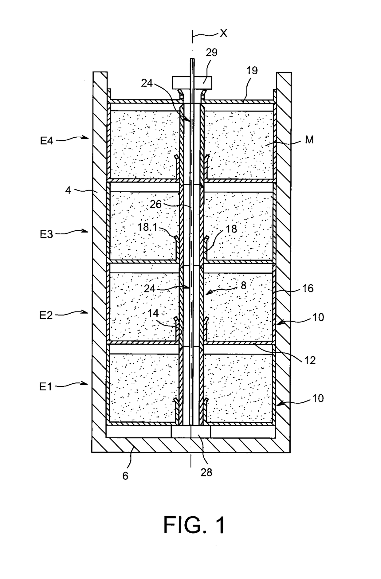
[0074]A hydrogen storage device according to the invention comprises one or several tanks containing storage material and a thermal management system designed to contribute and extract heat to release hydrogen and store the latter in the storage material respectively.

[0075]An example of such a device is illustrated in FIG. 5 and will be subsequently described in detail.

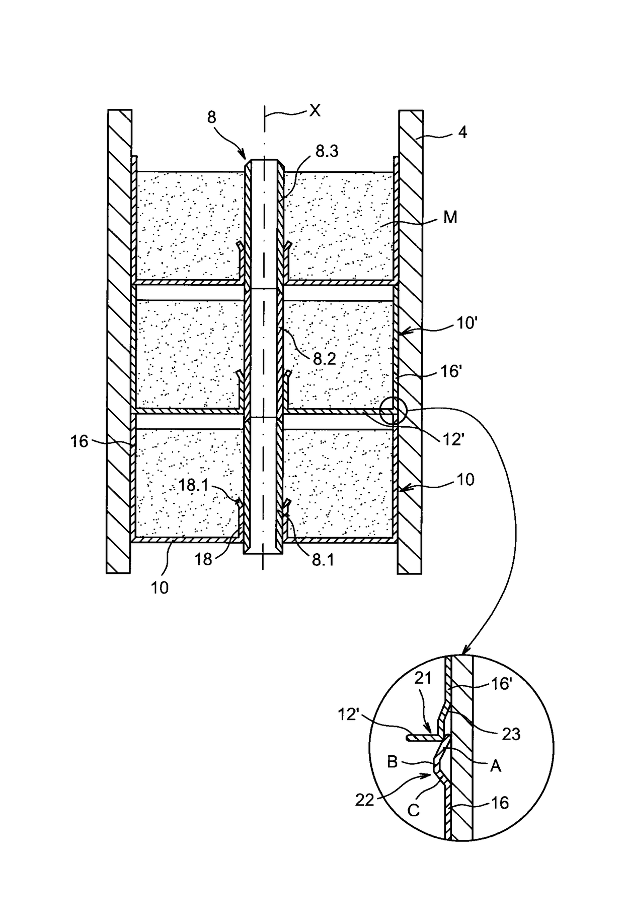
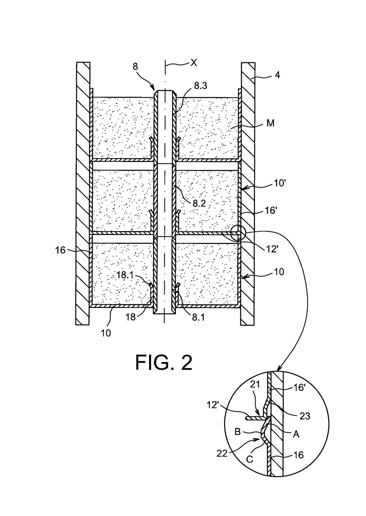
[0076]An example of embodiment of a tank of storage material represented diagrammatically can be seen in FIG. 1.

[0077]The tan...


PUM

PropertyMeasurementUnit
vertex angleaaaaaaaaaa
sizeaaaaaaaaaa
vertex angleaaaaaaaaaa

Abstract

A hydrogen storage material tank including a shell along a longitudinal axis, a hydrogen supply and collection duct along a longitudinal axis, a stack of plural cups around the duct, wherein each cup includes a base perpendicular to the longitudinal axis, a passage allowing installation of the cup around the duct, an outer wall perpendicular to the base, in contact with the shell and an inner wall perpendicular to the base and in contact with the duct, wherein each cup is force-fitted on the duct and each cup includes a mechanism allowing mutual engagement of the cups in one another by mechanical deformation of free ends of the outer walls of the cups.

Description

TECHNICAL FIELD AND PRIOR ART[0001]The present invention concerns a hydrogen storage tank comprising metal hydrides and a hydrogen storage device comprising at least such a tank.[0002]Alternative energies to replace petroleum are being sought owing in particular to the reduction in petroleum reserves. Hydrogen represents one of the promising vectors for these energy sources and can be used in fuel cells to produce electricity.[0003]Hydrogen is an element that is found ubiquitously in the universe and on Earth; it can be produced from natural gas or other hydrocarbons, but also by simple electrolysis of water using electricity produced by solar or wind power.[0004]Hydrogen fuel cells are already used in certain applications, in motor vehicles for example, but are still uncommon, particularly owing to the precautions to be taken and the difficulties in storing hydrogen.[0005]Hydrogen can be stored in compressed form at between 350 and 700 bars, which raises safety problems. Provision ...

Claims


Application Information

Patent Timeline
Patent Type & Authority Patents(United States)
IPC IPC(8): B65D85/00F17C11/00F17C1/12
CPCF17C11/005F17C1/12F17C2203/0362F17C2209/22Y02E60/321Y02E60/324Y10T29/49908Y02E60/32
Inventor ELIE, MANONCHAISE, ALBINGILLIA, OLIVIERPLANQUE, MICHEL
Owner COMMISSARIAT A LENERGIE ATOMIQUE ET AUX ENERGIES ALTERNATIVES
Why Eureka
Try Eureka