Autonomous pipeline inspection using magnetic tomography

Active Publication Date: 2017-08-29
GOROSHEVSKIY VALERIAN +2
View PDF6 Cites 3 Cited by
  • Summary
  • Abstract
  • Description
  • Claims
  • Application Information

AI Technical Summary

Benefits of technology

[0012]The instant invention provides for an autonomous undersea vehicle (AUV) in a torpedo construction that is flexible and uses magnetic tomography (MTM) sensors in a manner whereby the AUV is adapted to move inside the pipeline to be inspected and has a flexible construction to enable the device to pass readily through pipeline turns, bends, branches.
[0013]The AUV apparatus is formed in a series of interconnected pod like elements that provide sufficient flexibility to easily navigate through the internal pipeline contours and can be positioned in a plurality of positions within the pipeline to achieve enough measurable information to map defects in the pipeline metallic surface.
[0021]In addition, the instant invention provides for additional torpedo elements or pods with MT sensors for a second series of measurements to improve processing.
[0023]The instant invention provides for the torpedo elements or pods to perform on the basis of non-contact with the pipeline surface and have a plastic cover to preclude collisions within the pipeline.
[0024]in addition, the torpedo elements or pods can be provided with wires attached to the external surface of the torpedo element or pod to clean the pipeline surface and to protect against collisions with pipeline walls.

Problems solved by technology

It is limited to detection of an obvious bole m the pipe leading to the product (oil or gas) leakage or detection of the free sagging.

Method used


Image

  • Autonomous pipeline inspection using magnetic tomography
  • Autonomous pipeline inspection using magnetic tomography
  • Autonomous pipeline inspection using magnetic tomography

Examples


Embodiment Construction

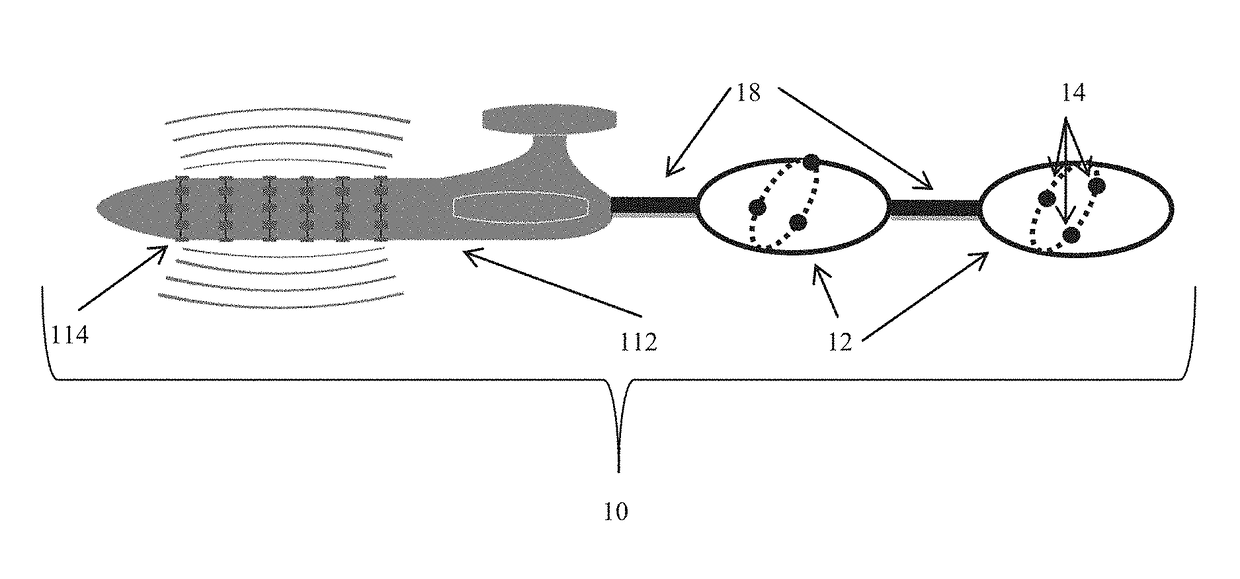
[0044]The term “remote,” as used herein is defined as being used from a substantial distance from a structure under testing. The term is used to signify that a sensor, as defined herein, is not necessarily located in close proximity to the structure being tested. The preferred embodiment of the invention performs best when the distance between structure and sensors ranges from 1-50 meters, however, the term remote is intended to mean up to 15 times the diameter of the structure being surveyed. This makes the invention especially effective for testing structures located deep underground and underwater.

[0045]The term “threshold distance,” as used herein, is defined as an amount equal to 15 (fifteen) times the diameter of a structure being surveyed, or scanned. The term is used to describe the range of the device and method claimed herein (i.e. the maximum distance between a given structure and a device during operation).

[0046]The term “sensor,” or “sensors,” as used herein, is defined...


PUM

PropertyMeasurementUnit
diameteraaaaaaaaaa
depthsaaaaaaaaaa
anglesaaaaaaaaaa

Abstract

The present invention discloses a device and system for magnetographic analysis of mechanical flaws and defects along structures located underwater for example, metallic pipelines, utilizing an autonomous magnetic tomography method (MTM) apparatus based on the inverse magnetostrictive effect for magnetographic identification, in the form of an array of flexible autonomous undersea vehicle (AUV) torpedo constructions of interconnected elements or pods. The array of AUV torpedo constructions are flexibly linked together so that the device can readily navigate within the contours of pipeline to be inspected using the flow media as propulsion means or alternatively by means of independent motive means without interfering with the system flow. The torpedo construction elements or pods each contain three MTM sensors situated 120 degrees apart on a non-perpendicular cross section arrangement, and perform a variety of independent functions. e.g., data storage data, sensor data memory unit, odometer distance measurements, GPS location, geomagnetic navigation capability.

Description

CROSS-REFERENCE TO RELATED APPLICATIONS[0001]This application is a continuation-in-part, and incorporates fully by reference, of U.S. patent application Ser. No. 14 / 242,938 filed Apr. 2, 2014 claiming priority to U.S. Provisional Patent application No. 61 / 807,378, filed Apr. 2, 2013. The present application also claims priority to U.S. patent application Ser. No. 13 / 662,427, filed Oct. 27, 2012; now U.S. Pat. No. 8,447,532; and U.S. patent application Ser. No. 13 / 674,118 filed Nov. 12, 2012; now U.S. Pat. No. 8,542,127 and incorporate fully by reference.BACKGROUND OF THE INVENTION[0002]Field of the Invention[0003]This invention relates to underwater measurements, and particularly to pipeline inspection using an autonomous underwater vehicle (AUV) for monitoring of ground, underground, and subsea structures and facilitating inspection or other operations performed on or near the structures. The invention further relates to surveying the condition of ground, underwater and underground...

Claims


Application Information

Patent Timeline
Patent Type & Authority Patents(United States)
IPC IPC(8): B63G8/00G01N27/82G01N27/85G01N17/02
CPCG01N27/82B63G2008/008G01N17/02G01N27/85
Inventor GOROSHEVSKIY, VALERIANKAMAEVA, SVETLANAKOLESNIKOV, IGORIVLEV, LEONID
Owner GOROSHEVSKIY VALERIAN
Why Eureka
Try Eureka