Integrated optical assembly apparatus and integrated fabrication method for coupling optical energy

a fabrication method and optical assembly technology, applied in the direction of photomechanical equipment, instruments, optical elements, etc., can solve the problems of difficult to manufacture an exact refractive index profile with a high level of precision, poor coupling efficiency of optical fiber to high-index contrast waveguide, and inability to meet the exact refractive index profil

Active Publication Date: 2017-08-29
PARTOW TECH LLC
View PDF33 Cites 29 Cited by
  • Summary
  • Abstract
  • Description
  • Claims
  • Application Information

AI Technical Summary

Problems solved by technology

The GRIN lens method disclosed in these publications requires a precise control of refractive index profile, and it is generally difficult to manufacture an exact refractive index profile with a high level of precision.
Because the mode size of a nano-waveguide is very small compared to the mode size of an optical fiber (i.e. typically less than 1 micron for a nano waveguide, compared to 10 microns for an optical fiber), the coupling efficiency from an optical fiber to a high-index contrast waveguide is very poor.
Furthermore, due to a large diffraction of light, the coupling efficiency between semiconductor lasers and planar optical waveguides is often unsatisfactory.

Method used


Image

  • Integrated optical assembly apparatus and integrated fabrication method for coupling optical energy
  • Integrated optical assembly apparatus and integrated fabrication method for coupling optical energy
  • Integrated optical assembly apparatus and integrated fabrication method for coupling optical energy

Examples


Embodiment Construction

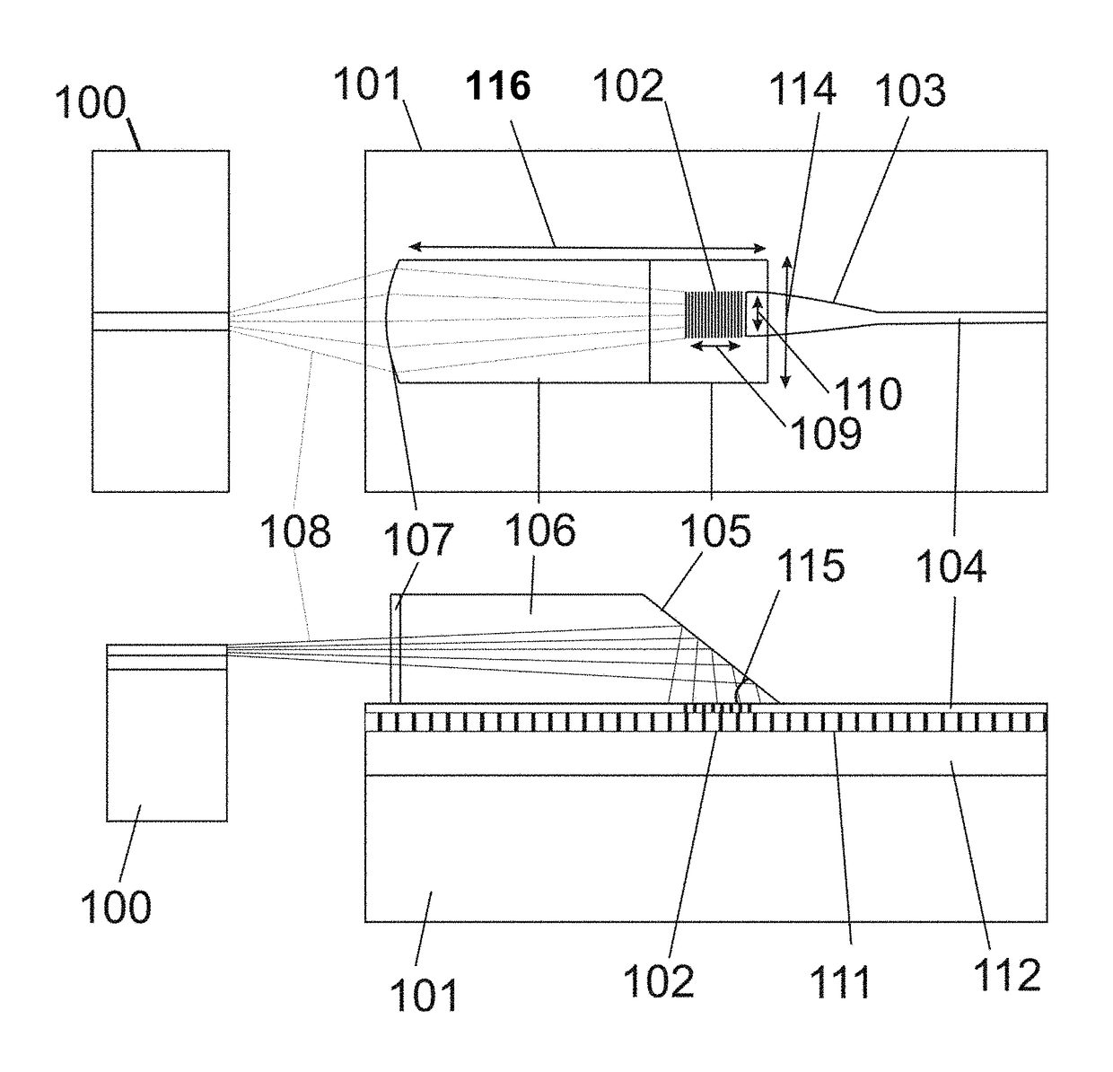
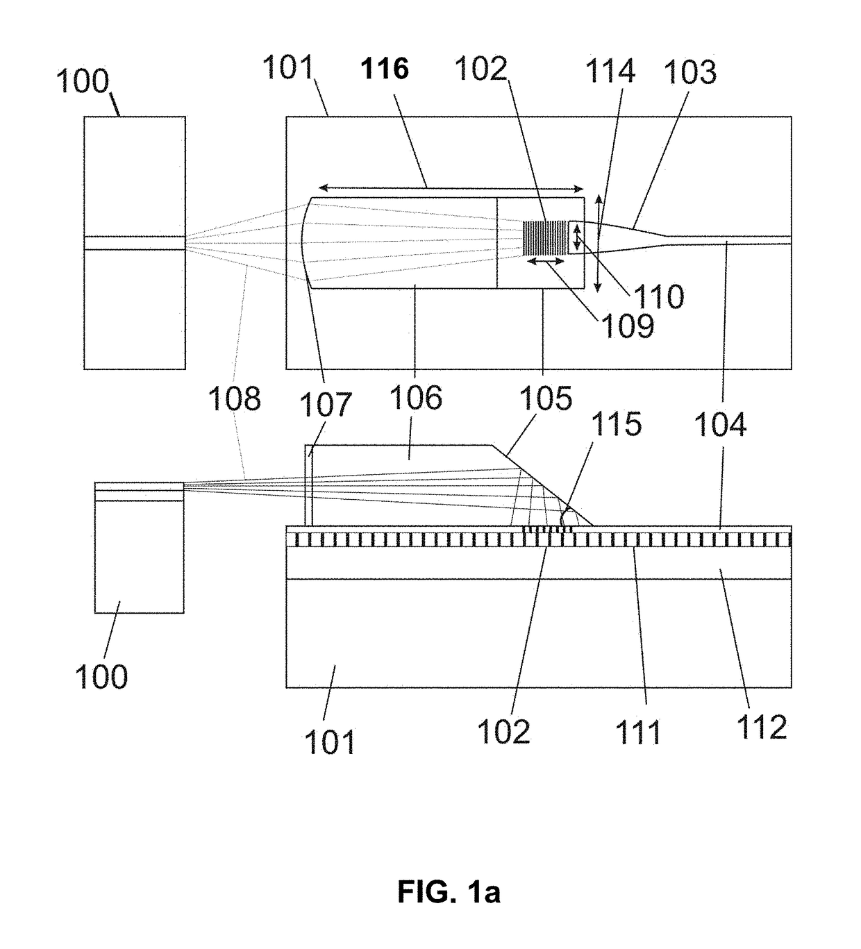
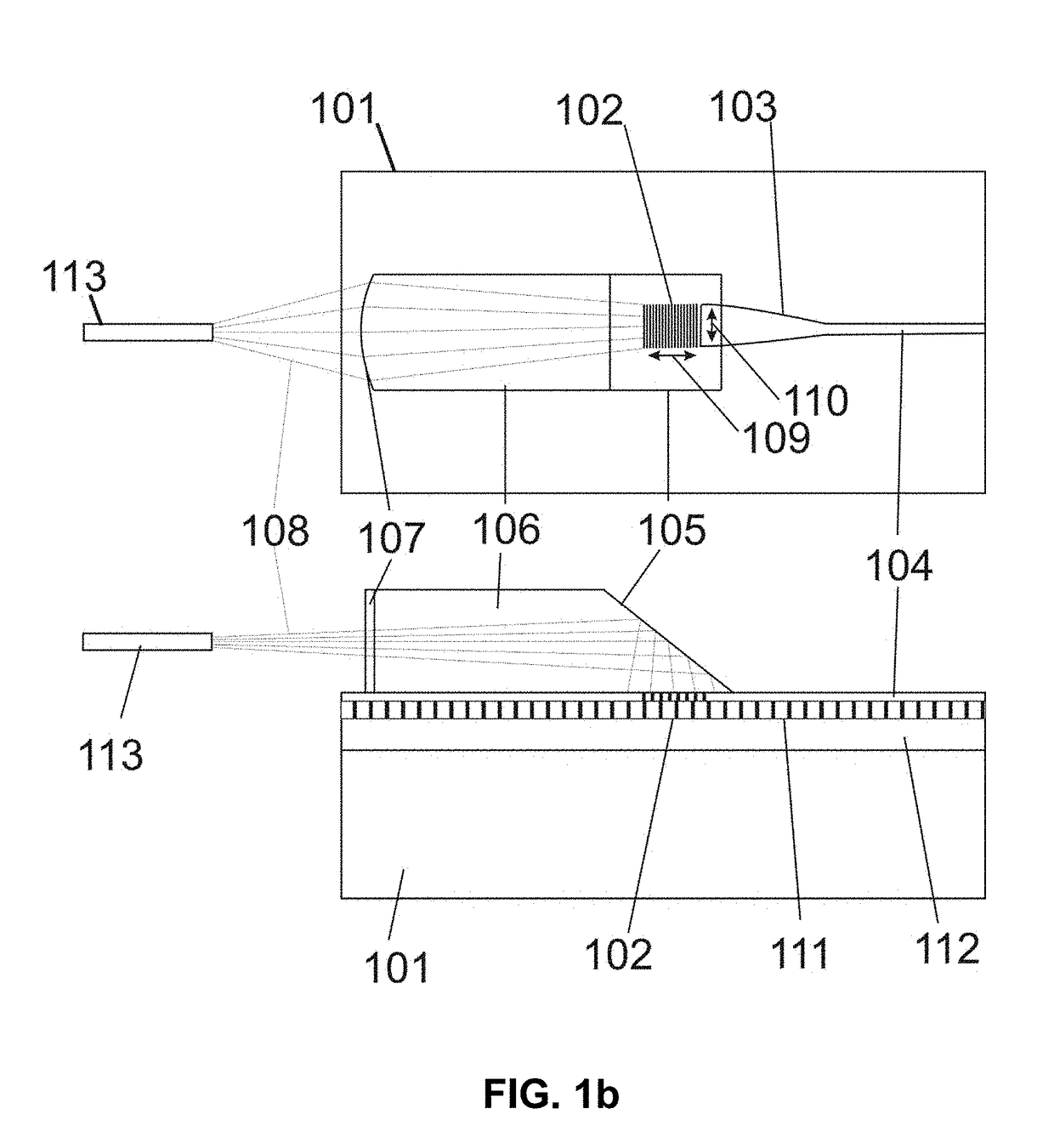
[0043]Specific embodiments of the invention will now be described in detail with reference to the accompanying figures. Like elements in the various figures are denoted by like reference numerals for consistency.

[0044]In the following detailed description of embodiments of the invention, numerous specific details are set forth in order to provide a more thorough understanding of the invention. However, it will be apparent to one of ordinary skill in the art that the invention may be practiced without these specific details. In other instances, well-known features have not been described in detail to avoid unnecessarily complicating the description.

[0045]The detailed description is presented largely in terms of procedures, logic blocks, processing, and / or other symbolic representations that directly or indirectly resemble an optical waveguide production method, and optical coupler apparatuses and devices utilizing the optical waveguide production method, in accordance with various em...


PUM

PropertyMeasurementUnit
lengthaaaaaaaaaa
thicknessaaaaaaaaaa
focal lengthaaaaaaaaaa

Abstract

A novel optical assembly apparatus for coupling optical energy and a related method for creating the novel optical assembly apparatus are disclosed. In one embodiment, the novel optical assembly apparatus includes a high-index contrast waveguide constructed on a semiconductor die or another base substrate with an aligned optical coupling section, a grating coupler etched onto a surface, a micro mirror with an acute angle relative to the surface, and a waveguide taper that narrows an optical beam width. A light ray entered into the optical coupling section is redirected by the micro mirror to form a perpendicular ray entry angle with the grating coupler. The grating coupler then efficiently couples the light ray with the waveguide taper, which in turn narrows the optical beam width. The light ray may originate from a semiconductor die or from an optical fiber, which is purposefully aligned with the high-index contrast waveguide.

Description

FIELD OF THE INVENTION[0001]The present invention generally relates to a method for production of optical elements to produce an optical integrated circuit. Furthermore, the present invention also relates to a method for coupling optical energy from an optical fiber to high-index contrast optical waveguides. Moreover, the present invention introduces a method to achieve a wavelength tunable laser module. In addition, the method introduced here relates to integrated assembly of semiconductor lasers with lithium niobate high-index contrast waveguides and optical fibers to create an optical integrated circuit. Furthermore, the present invention introduces a method for making high-index contrast waveguide in lithium niobate and lithium tantalate.BACKGROUND OF THE INVENTION[0002]In numerous electronic communication applications, optical assemblies are used in various optical circuits. A typical optical assembly may comprise an optical source, an optical circuit that modulate, filter, mix...

Claims


Application Information

Patent Timeline
Patent Type & Authority Patents(United States)
IPC IPC(8): G02B6/32G03F7/00G02B6/122G02B6/42G02B6/124G03F7/20G03F7/16G02B6/12
CPCG02B6/124G02B6/4214G02B6/4203G02B6/1228G02B6/1223G03F7/0005G03F7/2022G03F7/16G02B2006/12107G02B2006/12104G02B6/305G02B6/34
Inventor RABIEI, PAYAM
Owner PARTOW TECH LLC
Why Eureka
Try Eureka