Electrostatic atomizer

Active Publication Date: 2017-09-19
SUMITOMO CHEM CO LTD
View PDF26 Cites 0 Cited by
  • Summary
  • Abstract
  • Description
  • Claims
  • Application Information

AI Technical Summary

Benefits of technology

[0023]The present invention yields an effect of preventing the occurrence of a start-up period in which a spray content is lower, at the beginning of atomization.
[0024]The present invention yields an effect of making it possible to st

Problems solved by technology

For example, in a case where the electric field is weak, atomization becomes unstable and the electrostatic atomizer itself is wetted due to spray-back (a phenomenon in which sprayed droplets come back to a device side).
However, the method is ineffective in

Method used


Image

  • Electrostatic atomizer
  • Electrostatic atomizer
  • Electrostatic atomizer

Examples


examples

1. Studies on Atomization Characteristics of Electrostatic Atomizers—1

[0110]Three types of electrostatic atomizers A to C including three types of reference electrodes A to C, respectively, were prepared and atomization characteristics of each electrostatic atomizer were studied.

[0111]The following describes basic configurations of the electrostatic atomizers A to C. Note that the configurations of the electrostatic atomizers A to C are identical except that each of the electrostatic atomizers A to C includes a different reference electrode.

[0112]Atomized liquid droplet: a liquid droplet consisting of 10% of an aromatic compound, 79% of monomethylether, 8% of isoparaffin, and 3% of a sodium acetate solution;

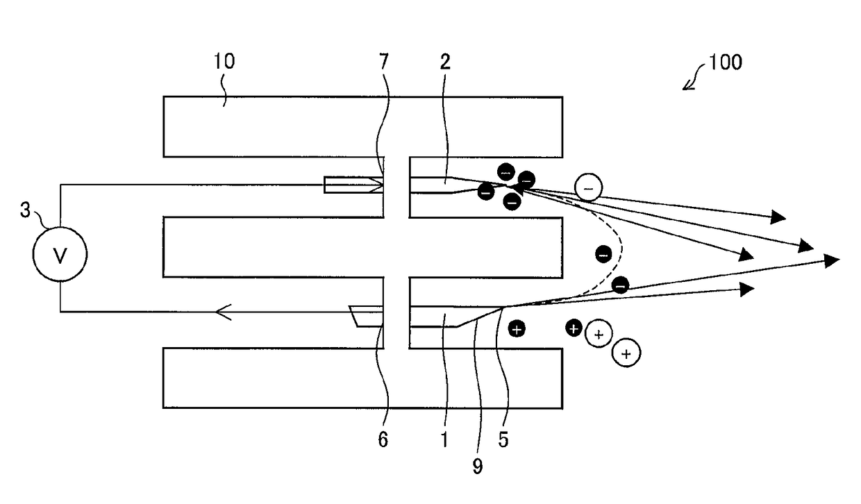
[0113]Spray electrode 1: a spray electrode made of stainless steel and having an outer diameter of 0.4 mm and an inner diameter of 0.2 mm;

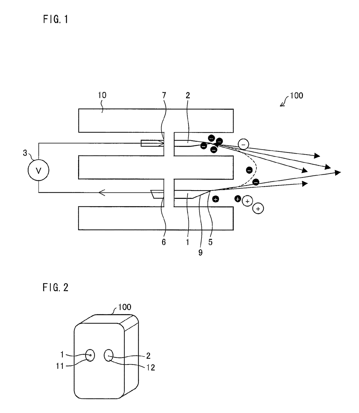
[0114]Dielectric 10: a dielectric made of polypropylene;

[0115]Opening 11: a circular opening having a diameter of 8 mm;

[0116]Opening 12: a cir...


PUM


Abstract

An electrostatic atomizer (100) includes: a spray electrode (1); a reference electrode (2); a current control section (24) for controlling a value of a current flowing through the reference electrode (2); and a voltage application section (22) for applying a voltage across the spray electrode (1) and the reference electrode (2), based on the value of the current controlled by the current control section (24), the reference electrode (2) having a tip whose shape has a specific curvature radius.

Description

CROSS REFERENCE TO RELATED APPLICATIONS[0001]This application is the National Phase of PCT / JP2014 / 050552, filed Jan. 15, 2014, which claims priority to Japanese Application No. 2013-004945, filed Jan. 15, 2013.TECHNICAL FIELD[0002]The present invention relates to an electrostatic atomizer that is excellent in atomization stability.BACKGROUND ART[0003]Conventionally, an atomizer which sprays a liquid in a container via a nozzle has been widely used in various fields. A known example of such an atomizer is an electrostatic atomizer which atomizes and sprays a liquid by Electro Hydrodynamics (EHD).[0004]The electrostatic atomizer forms an electric field near a tip of a nozzle and uses the electric field to atomize and spray the liquid at the tip of the nozzle. Typically, the electrostatic atomizer is configured such that an electric field is formed between two electrodes (a pin and a capillary which correspond to the nozzle) by application of a voltage across the two electrodes (see, f...

Claims


Application Information

Patent Timeline
IPC IPC(8): B05B5/057B05B5/025B05B5/08B05B5/053
CPCB05B5/0533B05B5/0255B05B5/057B05B5/0536B05B5/08
Inventor DAU, VAN THANHTEREBESSY, TIBOR
Owner SUMITOMO CHEM CO LTD
Why Eureka
Try Eureka