Liquid atomization device
- Summary
- Abstract
- Description
- Claims
- Application Information
AI Technical Summary
Benefits of technology
Problems solved by technology
Method used
Image

Examples
first embodiment
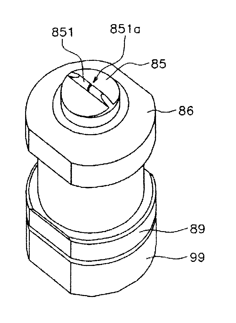
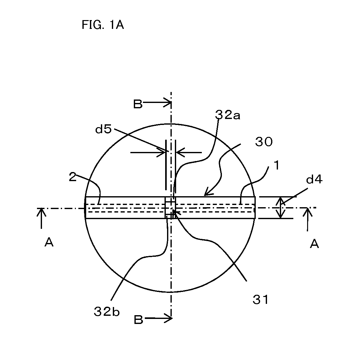
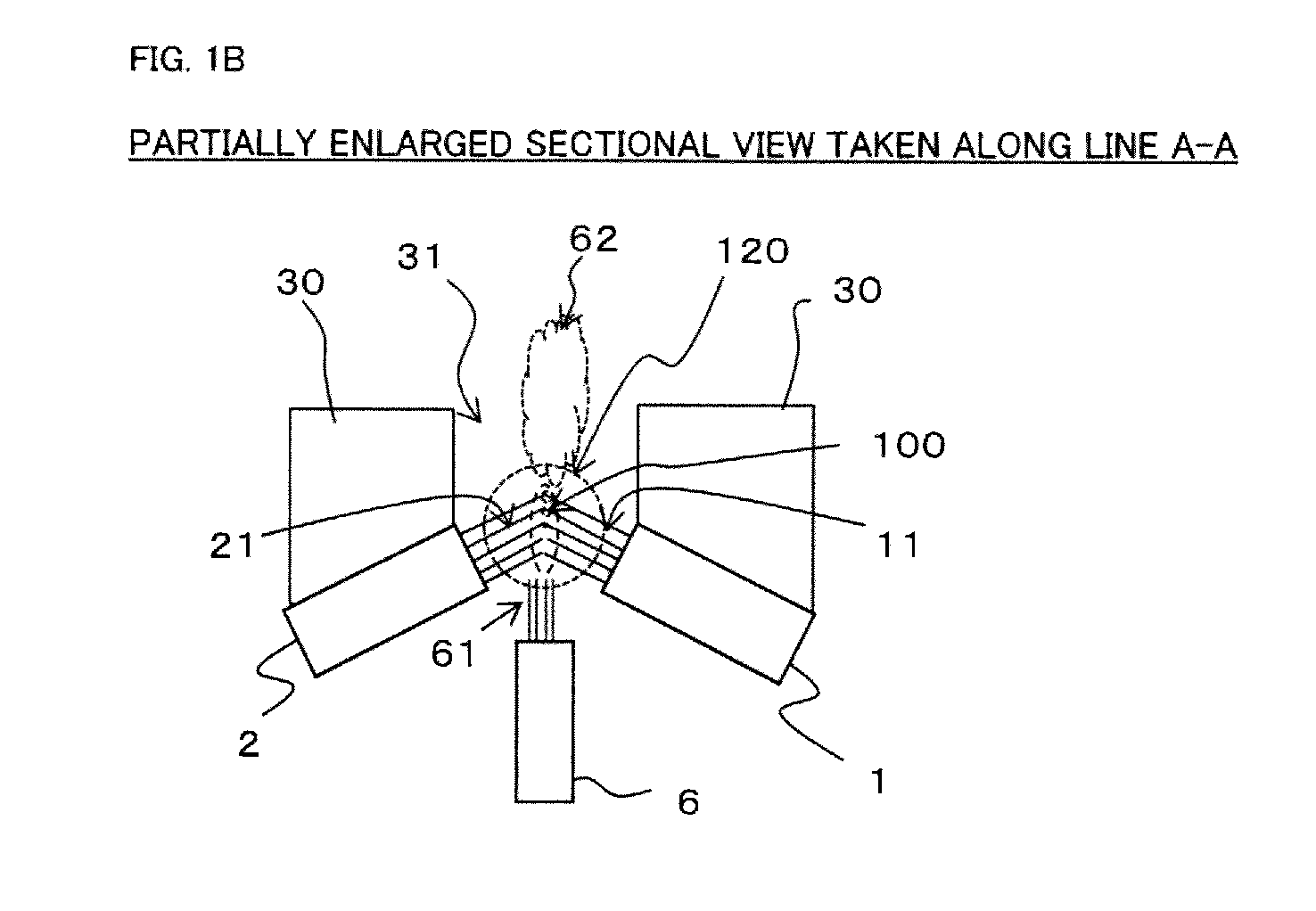
[0067]A liquid atomization device of a first embodiment will be described with reference to FIGS. 6A to 6D. The liquid atomization device shown in FIGS. 6A to 6D is configured as a nozzle device. FIGS. 7A to 7G are views for describing an outer cap portion. A first gas orifice 81 constituting a first gas spray unit and a second gas orifice (not shown) constituting a second gas spray unit are disposed so as to cause gas flows to collide against each other with a collision angle (α)=110°. Their orifice cross sections are square.
[0068]As shown in FIG. 6B, gas is supplied from a gas passage 80. The gas passage 80 is connected to a compressor (not shown). By controlling the compressor, a spray amount and spray speed of gas can be set. The gas passage 80 is in communication with both the first gas orifice 81 and second gas orifice. Spray amounts and spray speeds (flowing speeds) of gases sprayed from the first gas orifice 81 and the second gas orifice are set equal to (or substantially eq...
example 1
[0076]Using the liquid atomization device having the configuration shown in the first embodiment, presence or absence of generation of dew was evaluated. Each of the spray slit 851a of the projection 851 in Example 1 had a width (d4) of 1 mm, a slit depth (d6) of 0.95 mm, a slit interval (d5) of 0.3 mm, an inclination angle θ of the restriction portions 852a and 852b was 60°, a rectangular cross section of each of the first and second gas orifices had a slit width (d1) of 0.47 mm, a slit depth (d11) of 0.57 mm, and a diameter of a cross section of the liquid orifice tip end was φ0.35 mm. Air was used as gas, and water was used as liquid. Air pressure Pa, water pressure Pw, a spray angle, average particle diameters (SMD), and an amount of dew were evaluated based on the following two cases: when an air amount Qa of gas spray was 10.0 (NL / min), a spray (water) amount Qw was 25.0 (ml / min), and when an air amount Qa of gas spray was 10.0 (NL / min), a spray (water) amount Qw was 50.0 (ml / ...
example 2
[0077]In Example 1, the inclination angle of each of the restriction portions 852a and 852b was set to 90°, the air amount Qa of gas spray was set to 10.0 (NL / min) and the spray (water) amount Qw was set to 50.0 (ml / min). Under this condition, air pressure Pa, water pressure Pw, and average particle diameters (SMD) at a central portion and both ends of the spray pattern in the long diameter direction were evaluated. As comparison, the same evaluation was conducted without the restriction portions 852a and 852b (Comparative Example 2). The results are shown in Table 2. In Example 2, the average particle diameters of mist at the central portion and the both ends of the spray pattern in the long diameter direction were substantially equal to each other. In Comparative Example 2, on the other hand, the average particle diameter of mist on the both ends of the spray pattern in the long diameter direction was apparently greater. It was confirmed that, by providing the restriction portions...
PUM
| Property | Measurement | Unit |
|---|---|---|
| Angle | aaaaa | aaaaa |
| Angle | aaaaa | aaaaa |
| Diameter | aaaaa | aaaaa |
Abstract
Description
Claims
Application Information
 - Generate Ideas
- Intellectual Property
- Life Sciences
- Materials
- Tech Scout
- Unparalleled Data Quality
- Higher Quality Content
- 60% Fewer Hallucinations
Browse by: Latest US Patents, China's latest patents, Technical Efficacy Thesaurus, Application Domain, Technology Topic, Popular Technical Reports.
© 2025 PatSnap. All rights reserved.Legal|Privacy policy|Modern Slavery Act Transparency Statement|Sitemap|About US| Contact US: help@patsnap.com