Minimal contact edge ring for rapid thermal processing

a technology of supporting rings and annular edges, applied in the direction of chemically reactive gases, crystal growth processes, coatings, etc., can solve the problems of non-uniform temperature at different substrate regions, and the inability of support rings with annular edges to provide adequate temperature uniformity across the substrate, etc., to achieve the effect of reducing thermal coupling

Active Publication Date: 2017-09-19
APPLIED MATERIALS INC
View PDF17 Cites 0 Cited by
  • Summary
  • Abstract
  • Description
  • Claims
  • Application Information

AI Technical Summary

Benefits of technology

[0009]Embodiments of the present invention generally relate to a support ring for supporting a substrate during thermal processing in a process chamber. The support ring generally includes a ring body, an outer rib extending from a first surface of the ring body, a midrib extending from the first surface of the ring body, and a substrate support extending from a second surface of the ring body. The support ring reduces thermal coupling between a substrate and the support ring.

Problems solved by technology

It has been observed that variations in temperature gradients across the substrate can result in non-uniform processing of the substrate.
Non-uniform temperatures occur at different substrate regions because of non-uniform convection or conduction heat losses or gains from regions of the substrate in contact with the support (or other chamber components) versus substrate regions not in contact with the support.
Support rings having an annular edge can fail to provide adequate temperature uniformity across the substrate in rapid heating rate processes, for example, processes having heating rates of at least about 200° C. / second in a rapid thermal processing (RTP) system.
In these processes, the difference in heating rates between the support ring and the substrate generates temperature gradients along the periphery of the substrate that become unacceptably high during the heating process step.
It is particularly difficult to achieve temperature uniformity across the substrate especially when the substrate is heated at reduced pressure.

Method used


Image

  • Minimal contact edge ring for rapid thermal processing
  • Minimal contact edge ring for rapid thermal processing
  • Minimal contact edge ring for rapid thermal processing

Examples


Embodiment Construction

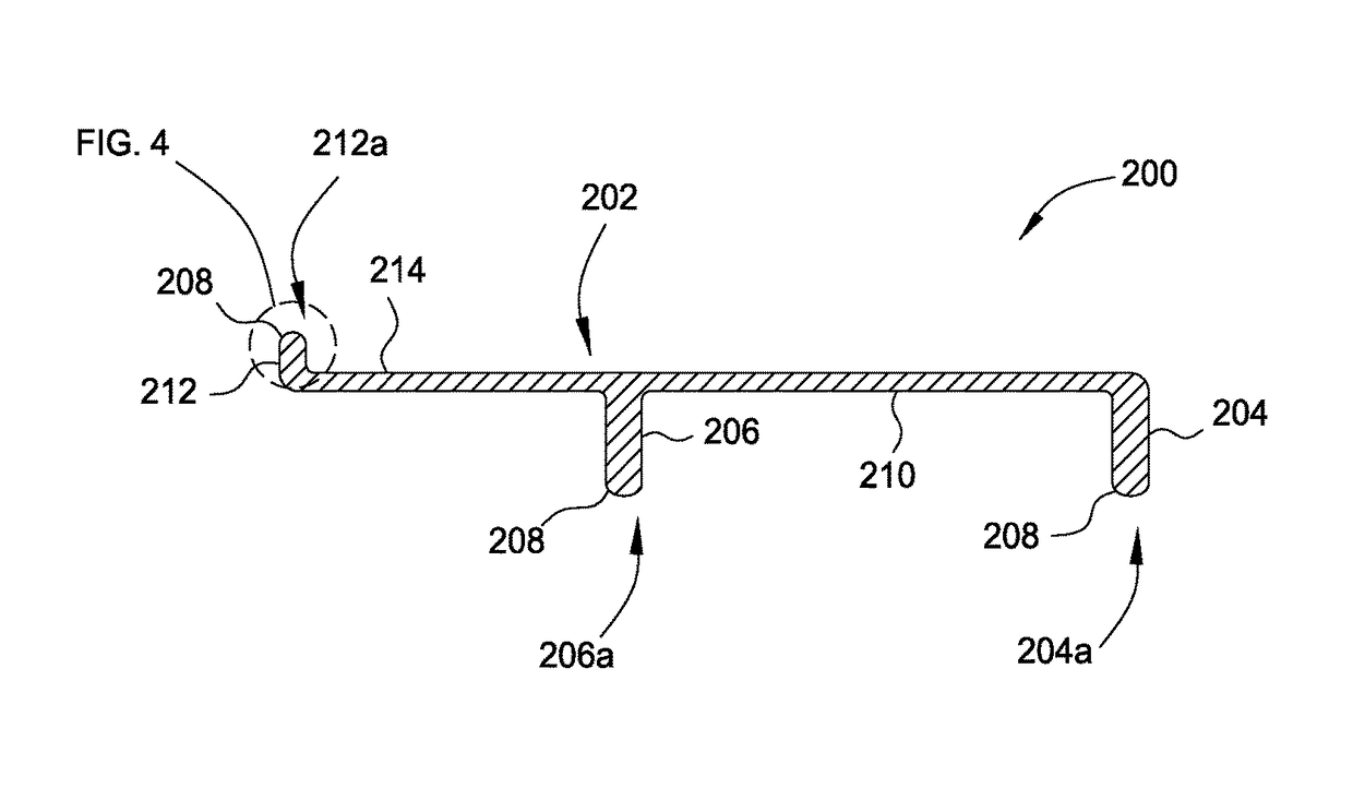
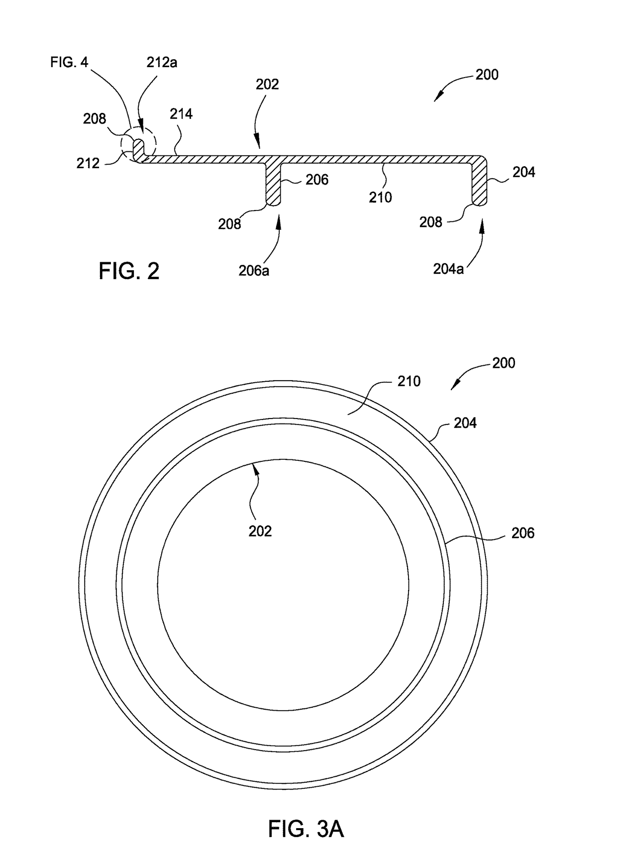
[0019]Embodiments of the present invention generally relate to a support ring for supporting a substrate during thermal processing in a process chamber. The support ring generally includes a ring body, an outer rib extending from a first surface of the ring body, a midrib extending from the first surface of the ring body, and a substrate support extending from a second surface of the ring body. The support ring reduces thermal coupling between a substrate and the support ring.

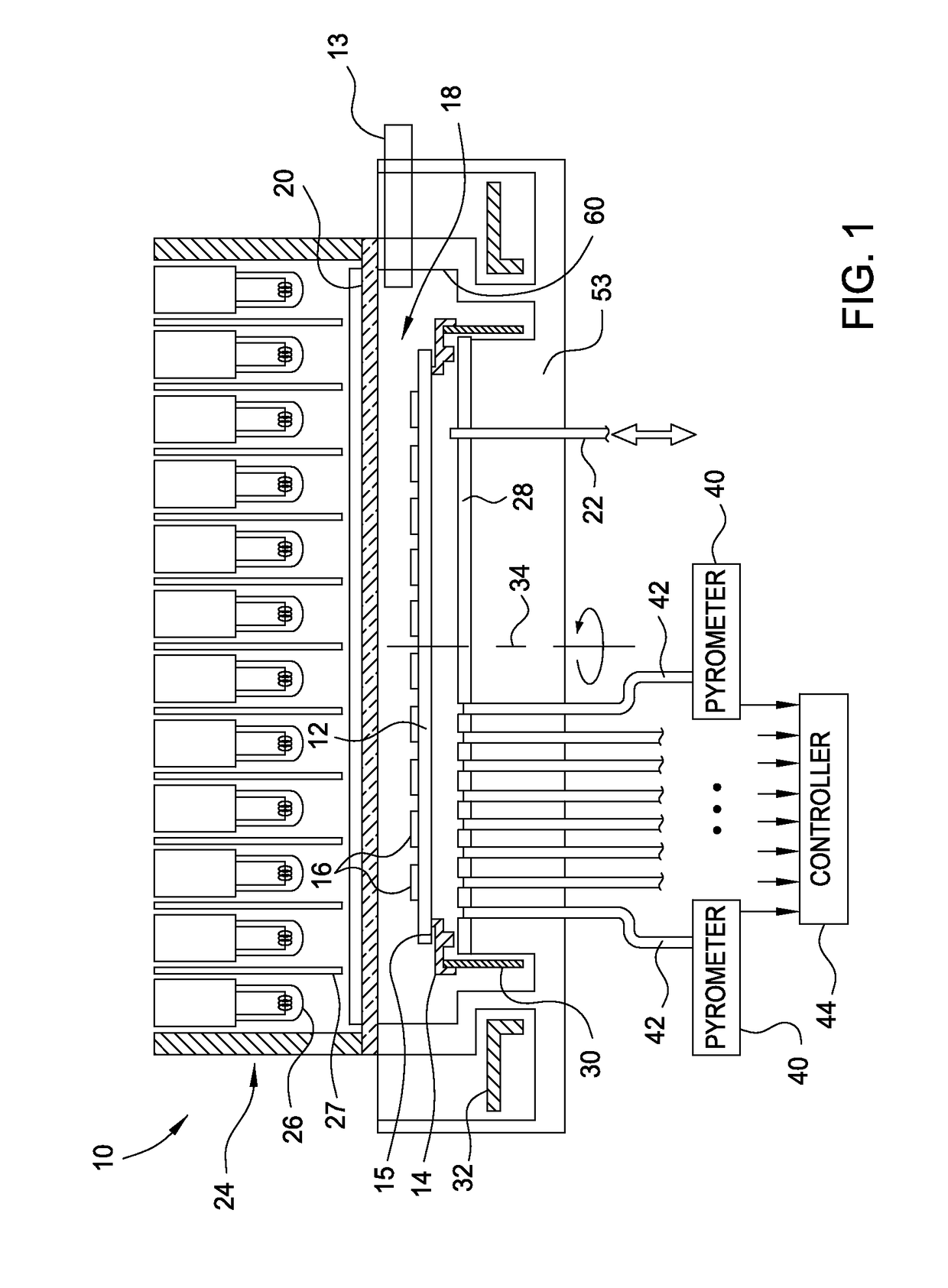
[0020]FIG. 1 schematically represents a rapid thermal processing chamber 10. A substrate 12, for example, a semiconductor substrate such as a silicon substrate to be thermally processed is passed through the valve or access port 13 into the process area 18 of the processing chamber 10. The substrate 12 is supported on a periphery thereof by an annular support ring 14. The substrate 12 may be oriented such that processed features 16 already formed in a front surface of the substrate 12 face upwardly toward a pro...


PUM

PropertyMeasurementUnit
heightaaaaaaaaaa
widthaaaaaaaaaa
aspect ratioaaaaaaaaaa

Abstract

Embodiments of the present invention generally relate to a support ring for supporting a substrate during thermal processing in a process chamber. The support ring generally includes a ring body, an outer rib extending from a first surface of the ring body, a midrib extending from the first surface of the ring body, and a substrate support extending from a second surface of the ring body. The support ring reduces thermal coupling between a substrate and the support ring.

Description

CROSS-REFERENCE TO RELATED APPLICATIONS[0001]This application claims benefit of U.S. Provisional Patent Application Ser. No. 61 / 782,150, filed Mar. 14, 2013, which is herein incorporated by reference.BACKGROUND OF THE INVENTION[0002]Field of the Invention[0003]Embodiments of the present invention generally relate to a support ring to support a substrate in a process chamber.[0004]Description of the Related Art[0005]In the processing of substrates, such as semiconducting substrates, the substrate is placed on a support in a process chamber and suitable processing conditions are maintained in the process chamber. For example, the substrate can be heated in a controlled heating cycle to thermally process the substrate. The substrate can be heated, for example, by an array of heating lamps disposed above and / or below the substrate in the chamber. Thermal processing can be used to anneal a layer that has been ion-implanted on the substrate, perform thermal oxidation or nitridation proces...

Claims


Application Information

Patent Timeline
Patent Type & Authority Patents(United States)
IPC IPC(8): H01L21/683H01L21/687H01L21/67C23C16/458C30B25/12
CPCH01L21/68735H01L21/67115C23C16/4585C30B25/12H01L21/67248
Inventor PAN, HENGBAUTISTA, KEVIN J.
Owner APPLIED MATERIALS INC
Why Eureka
Try Eureka