Diagnostic test device with audible feedback

a diagnostic test and feedback technology, applied in the field can solve the problems of user anxiety, user interface disconnect, limited user interface of diagnostic test devices, etc., and achieve the effects of improving user experience, improving understanding of results, and increasing communication

Active Publication Date: 2017-09-26
CHURCH & DWIGHT CO INC
View PDF46 Cites 1 Cited by
  • Summary
  • Abstract
  • Description
  • Claims
  • Application Information

AI Technical Summary

Benefits of technology

[0007]The present disclosure relates to diagnostic test devices that include elements useful for carrying out an assay and for providing information related to the assay in an audible format. As an illustrative example, a pregnancy test device can be provided and can include elements for carrying out a test on a fluid sample applied to a receiving member so as to identify the presence of human chorionic gonadotropin (hCG) in the sample that is indicative of a pregnancy status. Such test device beneficially can include further elements that enable the test device to provide a variety of audible indices relating to the operation and results of the assay. Test devices according to the present disclosure thus can provide for increased communication from the test device to a user thereof and make the test device easier for the user to operate, improve understanding of the results of the included assay, and increase user comfort with the test device and user assurance in the reliability of the test device.

Problems solved by technology

Nevertheless, user interface with diagnostic test devices remain limited.
For example, user interface disconnect can lead to user anxiety, such as in relation to uncertainty over the elapsed time between starting a test and obtaining the test result.
During this time, there also can be anxiety over whether the test is indeed progressing normally.
For example, although some test devices include a liquid crystal display (LCD) digital readout that can display a static or blinking clock as indicia of a progressing test, such interface can be sufficiently limited so as to not meet user expectations and overcome anxiety.

Method used


Image

  • Diagnostic test device with audible feedback
  • Diagnostic test device with audible feedback
  • Diagnostic test device with audible feedback

Examples


Embodiment Construction

[0029]The present disclosure now will be described more fully hereinafter with reference to specific embodiments and particularly to the various drawings provided herewith. Indeed, the disclosure may be embodied in many different forms and should not be construed as limited to the embodiments set forth herein; rather, these embodiments are provided so that this disclosure will satisfy applicable legal requirements. As used in the specification, and in the appended claims, the singular forms “a,”“an,”“the,” include plural referents unless the context clearly dictates otherwise.

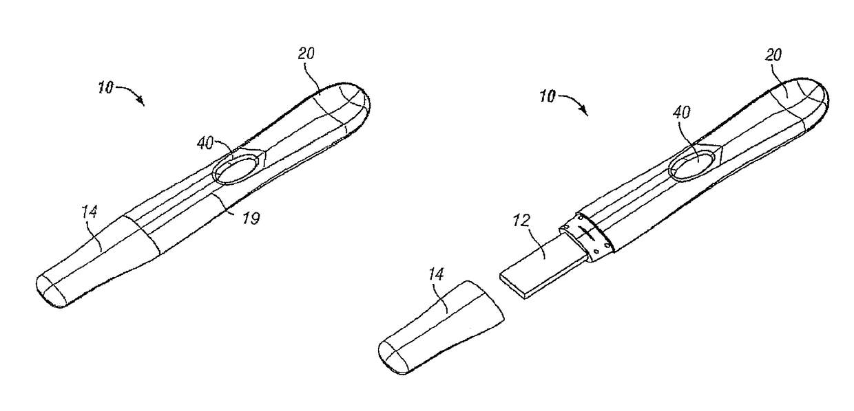
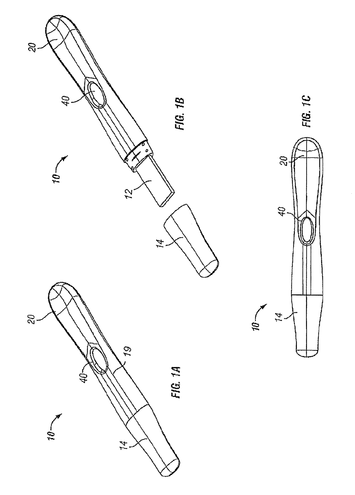
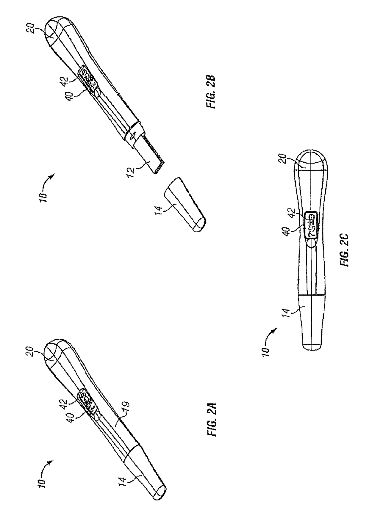
[0030]In one aspect, the present disclosure relates to a test device, such as an over-the-counter (OTC) or point of care (POC) test device, for detecting an analyte in a sample. The device generally includes components suitable for carrying out an assay, such as a lateral flow assay, and also includes components suitable for communicating information relating to the assay to an individual.

[0031]The test compone...


PUM

PropertyMeasurementUnit
volumeaaaaaaaaaa
transparentaaaaaaaaaa
color changeaaaaaaaaaa

Abstract

Diagnostic test devices improve communication to a user thereof through provision of audible output. The test device can include a test member, such as lateral flow assay test strip. The test device further includes an electronic communication circuit that can comprise an audio output element as well as a microcontroller. Other elements in the electronic communication circuit includes one or more sensor elements, a display element, and one or more switching elements.—Methods provide indicia for operation of a test device that comprise steps for assembly of a diagnostic test device that provides for audio output.

Description

CROSS-REFERENCE TO RELATED APPLICATION[0001]This application is related to U.S. Provisional Patent Application Ser. No. 61 / 779,615 filed Mar. 13, 2013 and takes priority therefrom.FIELD OF THE DISCLOSURE[0002]The present disclosure relates to diagnostic test devices that provide user connectivity. More particularly, the test devices include elements that provide for specific feedback to the user, such as through audible means.BACKGROUND[0003]Many types of ligand-receptor assays have been used to detect the presence of various substances in body fluids, such as urine, saliva, or blood. Some commercially available assays are designed to make a quantitative determination, but in many circumstances all that is required is a qualitative positive / negative indication. Examples of such qualitative assays include blood typing, pregnancy testing, and many types of urinalysis.[0004]U.S. Pat. No. 6,485,982, which is incorporated herein by reference in its entirety, describes a diagnostic test c...

Claims


Application Information

Patent Timeline
Patent Type & Authority Patents(United States)
IPC IPC(8): G08B23/00G08B21/18G01N33/74A61B5/00A61B5/145G01N33/543G08B3/00
CPCG08B21/18A61B5/145A61B5/741A61B5/7415G01N33/54386G01N33/74G08B3/00G01N33/54388
Inventor PALMER, MATHEWSANDERS, GILES H. W.WOODER, NICHOLAS J.NAZARETH, ALBERT R.SNOWDEN, TIMOTHYROMANOSCHI, OVIDIU
Owner CHURCH & DWIGHT CO INC
Why Eureka
Try Eureka