Apparatus and method to maximize vehicle functionality and fuel economy with improved drivability during engine auto stop-start operations

a technology of engine stop-start operation and vehicle, applied in the direction of engine starters, mechanical apparatuses, machines/engines, etc., can solve the problems of current limitation of electric load devices, and achieve current limitation

Active Publication Date: 2017-10-03
FORD GLOBAL TECH LLC
View PDF41 Cites 9 Cited by
  • Summary
  • Abstract
  • Description
  • Claims
  • Application Information

AI Technical Summary

Benefits of technology

[0007]In one aspect of the invention, the system and routine described herein allows an operation of electrical load devices in vehicles during an engine-off sequence for an engine auto stop-start operation. The system includes a primary power source and a secondary power source where the respective power sources are electrically isolated from one another during an auto stop-start operation. During an engine-off sequence, the respective power sources are electrically isolated from one another where electrical loads are supplied energy by the secondary power source while the primary power source is used to actuate the starter and the engine. The electrical load devices of the vehicle maintain their operation by drawing energy only from the secondary power source. This provides the following advantages, the primary power source is not drained of energy from operation of the electrical load devices during the engine-off sequence; the secondary power source is not drained from an in-rush current draw by a starter motor during an engine re-start operation since the starter motor is electrically disconnected from the secondary power source during the engine auto stop-start operation; electrical loads are still operational during the engine-off period; and loads sensitive to low voltage are protected and are assured that a sufficient amount of power is provided at all times during the auto-stop sequence.
[0008]In addition, the electrical load devices may be current limited during the engine auto stop-start operation; however, the current-limiting is performed in a manner that is not degradable in a noticeable way to the driver. This provides the advantage of allowing devices to be conditionally operational as expected by a driver of the vehicle during an engine off sequence. This reduces complaints or warranty claims that a device was non-operational during a period when the vehicle was at an idling status.
[0009]Moreover, the system described herein provides a further advantage of providing full power to an electrical load device under extreme operating conditions. Capabilities of the power sources and power demands by the electrical load devices are monitored, and should extreme and continuous energy use by a respective electrical load device be demanded, the system will inhibit the engine auto stop-start functionality and start the internal combustion engine so sufficient power may be provided to the respective electrical load device from another power source or power generating device such as an alternator or motor-generator device.

Problems solved by technology

In addition, the electrical load devices may be current limited during the engine auto stop-start operation; however, the current-limiting is performed in a manner that is not degradable in a noticeable way to the driver.

Method used


Image

  • Apparatus and method to maximize vehicle functionality and fuel economy with improved drivability during engine auto stop-start operations
  • Apparatus and method to maximize vehicle functionality and fuel economy with improved drivability during engine auto stop-start operations
  • Apparatus and method to maximize vehicle functionality and fuel economy with improved drivability during engine auto stop-start operations

Examples


Embodiment Construction

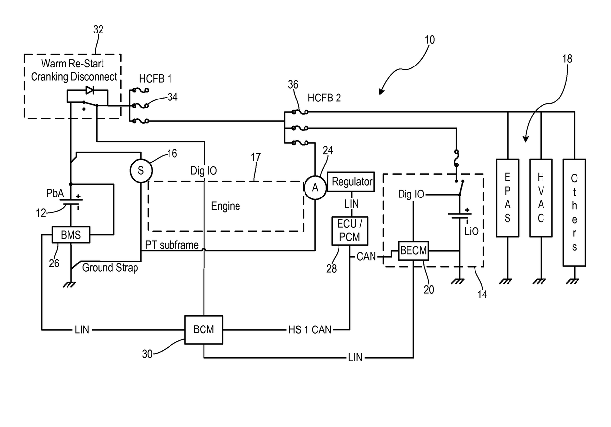
[0014]There is shown in FIG. 1, an electrical schematic architecture of a dual power supply system 10 for a vehicle equipped with auto stop-start functionality. For the purposes described herein, a vehicle equipped with auto stop-start functionality is defined as a Micro-Hybrid vehicle and / or Mild-Hybrid vehicle having two or more power sources. Micro-Hybrid vehicles include vehicles having more than one 12V power source. Typically Micro-Hybrid vehicles do not include power boost system to electrically power the drivetrain. Mild-Hybrid vehicle are vehicles that include two or more different power sources of different voltage levels (e.g., 12V / 48V, 12V / 110V). The Mild-Hybrid vehicles include an electric motor that may serve as a power booster and / or start-generator. The vehicles described hereinafter shall be referred to as auto stop-start equipped vehicles and is meant to include both Micro-Hybrid vehicles and Mild-Hybrid vehicles.

[0015]The dual power supply system 10 includes a pri...


PUM


Abstract

An auto stop-start equipped vehicle power management system includes a primary power source supplying energy to an electrical starter to crank a vehicle engine and a secondary power source coupled in parallel to the primary power source. The secondary power source supplies energy to electric loads during an engine auto stop-start operation. The electrical loads maintain vehicle subsystem functionality during the engine auto stop-start operation. The energy supplied to the electrical loads is current limited during the engine auto stop-start operation. A controllable switch decouples the secondary power source from the primary power source and starter motor during the engine auto stop-start operation. Operating parameters of the electrical loads are monitored during the engine auto stop-start operation. If a respective operating parameter threshold associated with the electrical loads is exceeded during the engine auto stop-start operation, then the vehicle engine is automatically restarted and the controllable switch is subsequently closed.

Description

CROSS REFERENCE TO RELATED APPLICATIONS[0001]Not Applicable.STATEMENT REGARDING FEDERALLY SPONSORED RESEARCH[0002]Not Applicable.BACKGROUND OF INVENTION[0003]The present invention relates in general to auto stop-start equipped vehicles and power management of high load devices during engine auto stop-start operations.[0004]Vehicles typically utilize a single 12V battery topology as a vehicle's power source; however, such systems have limited charge power capability. With the increasing demand of electric power in modern day vehicles, there is an increasing challenge to utilize all possible power sources that generate energy in the vehicle and maximize the use of these generated energy devices or systems. The maximum amount of energy that can be stored in such devices determines how other devices may be used or when energy can be provided to such devices.[0005]Vehicles capable of performing an engine stop-start operation utilize an internal combustion engine that is turned off when t...

Claims


Application Information

Patent Timeline
Patent Type & Authority Patents(United States)
IPC IPC(8): B60W30/18F02N11/08B60W10/06B60W10/26B60W30/00
CPCB60W30/18B60W10/06B60W10/26B60W30/18054F02N11/08F02N11/0866B60W30/00B60W2510/18B60W2510/202B60W2510/205B60W2510/305B60W2520/04B60W2710/06B60W2710/248F02N11/0814F02N2200/0808F02N2250/02Y02T10/48F02N2300/2011Y02T10/40
Inventor KHAFAGY, HAFIZ S.PEBLEY, KIRKBOUSE, WILLIAM J.DELJEVIC, ZELJKO
Owner FORD GLOBAL TECH LLC
Why Eureka
Try Eureka