
Method for reducing oscillations in offshore wind turbines

a wind turbine and oscillation reduction technology, which is applied in the direction of vessel movement reduction by jet/propeller, floating buildings, buoys, etc., can solve the problems of increasing difficulty in finding suitable locations for wind turbines on land, not always readily available, and a lot of opposition to the placement of wind turbines, so as to achieve power output and avoid dangerous resonance situations

Inactive Publication Date: 2017-10-03
GE RENEWABLE TECH WIND BV
View PDF17 Cites 6 Cited by
  • Summary
  • Abstract
  • Description
  • Claims
  • Application Information

AI Technical Summary

Benefits of technology

This patent describes using underwater thrusters on a wind turbine to reduce fluctuations in its performance. These thrusters can help the turbine maintain a steady pace without needing to change the way it pitches or compromising its power output. They can also prevent dangerous resonance situations that could occur naturally.

Problems solved by technology

It has become increasingly difficult to find suitable locations for wind farms on land.
On many occasions, there has been a lot of opposition against placement of wind turbines due mainly to the noise produced by the wind turbines and aesthetic effects of the placement of wind turbines.
Additionally, for wind turbines to be able work efficiently, a windy and open area free from trees and buildings etc. is needed which is not always readily available.
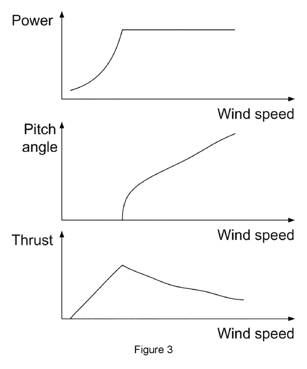
This adjustment leads to an ever changing thrust on the wind turbine.
An oscillating thrust may cause fore-aft oscillations of the wind turbine.
The variation of the pitch angle and the variation of thrust that comes with it may lead to fore-aft oscillations in onshore wind turbines as well.
Under certain circumstances, resonance of the wind turbine in such a fore-aft oscillation may become a problem.
A disadvantage of this method is that the maximum potential power output of the wind turbine is not achieved, because the ideal pitch angles are not employed.
Secondly, even though such an alternative pitch control has in some cases successfully been applied in wind turbines placed on land, they may not always be successful in offshore applications.
This is due to the fact that the oscillations may generally be of lower frequency for which there is a particular danger of resonance.

Method used


Image

  • Method for reducing oscillations in offshore wind turbines
  • Method for reducing oscillations in offshore wind turbines
  • Method for reducing oscillations in offshore wind turbines

Examples


first embodiment

[0033]FIG. 4a schematically illustrates an offshore wind turbine according to the present invention. The floating wind turbine 10 comprises a wind turbine tower 11, a nacelle 12 arranged on top of said tower and a rotor having a plurality of blades. The water level has been schematically indicated with reference sign 20.

[0034]The wind turbine tower 11 may comprise a buoyancy body and a ballast weight. Mooring lines 25 connected at the sea bed 30 serve to substantially keep the wind turbine in place and at least partially stabilize the floating wind turbine. The mooring lines 25 may be connected at stabilization arms 18. Although not clearly distinguishable in the side view provided in FIG. 4a, the stabilization arms 18 and mooring lines are not necessarily provided in the fore-aft direction or only in the fore-aft direction. In embodiments, the stabilization arms may e.g. extend in a radial direction away from the turbine tower. In other embodiments, the stabilization arms may form ...

second embodiment

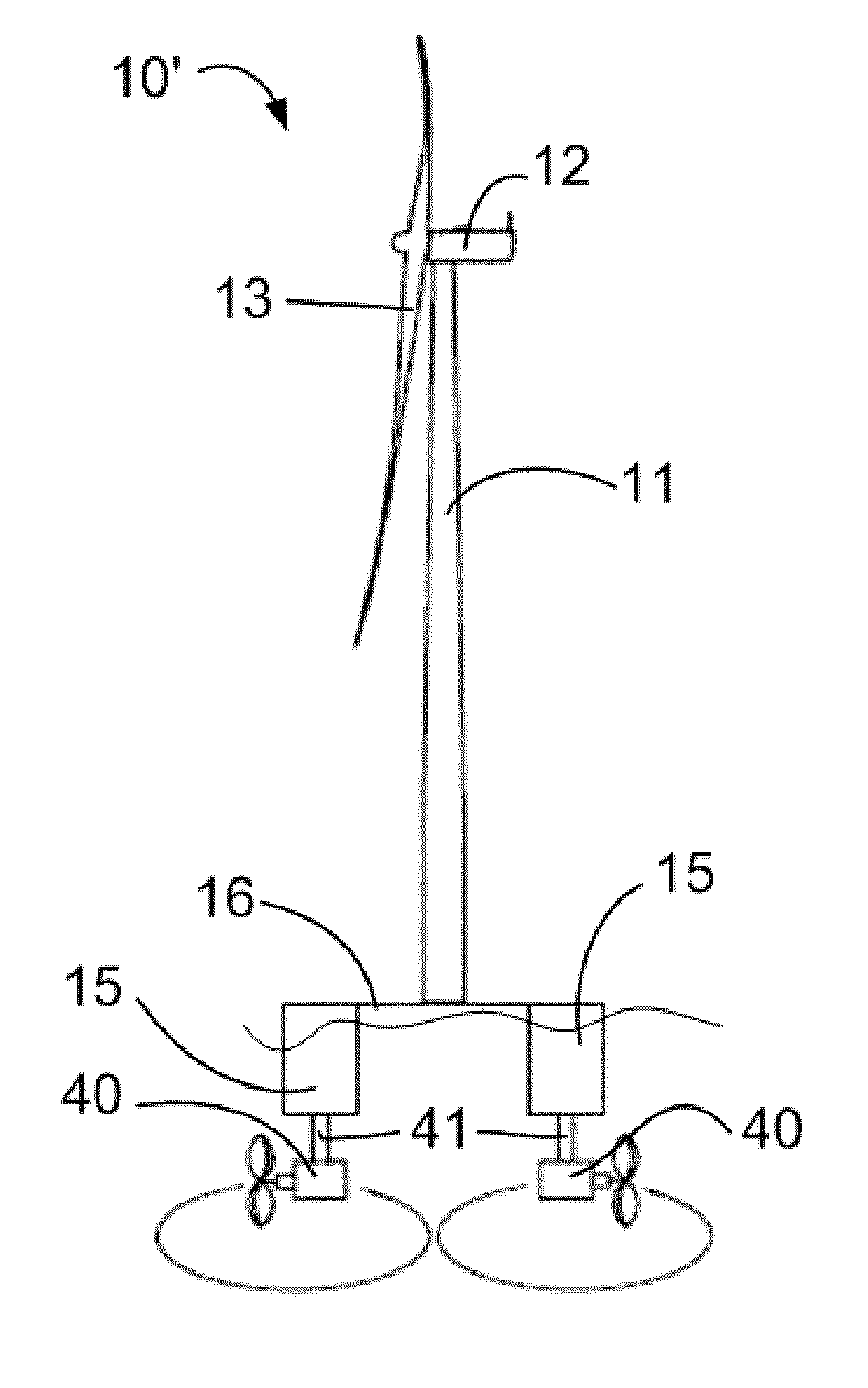
[0045]FIG. 4b shows a floating wind turbine 10′ in accordance with the present invention. The same reference signs have been used to indicate the same parts or components. In this example, the wind turbine 10′ comprises a platform 16 upon which the wind turbine tower 11 is located. The platform 16 is carried by a plurality of buoyancy tanks 15. In the side view of FIG. 4b, only two buoyancy tanks are shown. In embodiments of the invention, a wind turbine may comprise two, three, four or more of these buoyancy tanks surrounding the platform 16.

[0046]Two underwater propellers 40 are mounted on the bottom of the buoyancy tanks 15. Both propellers are adapted to be able to change their orientation, since they are mounted on rotatable shafts 41. The working principle is similar to what was shown before: in response to an oscillation, the propellers may be actuated. Their orientation and / or thrust may be adapted. And they may or may not be actuated at the same time.

[0047]In embodiments co...


PUM


Abstract

The invention relates to a method of reducing oscillations in an offshore wind turbine comprising one or more thrusters, the method comprising determining an oscillation of the offshore wind turbine and operating the one or more thrusters such that the oscillation is reduced. The invention further relates to an offshore wind turbine comprising one or more underwater thrusters, oscillation determination system for determining an oscillation of the wind turbine and a control system for operating the underwater thrusters in response to signals received from the oscillation determination system.

Description

[0001]The present invention relates to offshore wind turbines, and more particularly relates to a method for reducing oscillations in offshore wind turbines and to offshore wind turbines adapted for this purpose.BACKGROUND ART[0002]Modern wind turbines are commonly used to supply electricity into the electrical grid. Wind turbines of this kind generally comprise a rotor with a rotor hub and a plurality of blades. The rotor is set into rotation under the influence of the wind on the blades. The rotation of the rotor shaft either directly drives the generator rotor (“directly driven”) or through the use of a gearbox.[0003]Wind turbines are often grouped together in so-called wind farms. It has become increasingly difficult to find suitable locations for wind farms on land. On many occasions, there has been a lot of opposition against placement of wind turbines due mainly to the noise produced by the wind turbines and aesthetic effects of the placement of wind turbines. Additionally, f...

Claims


Application Information

Patent Timeline
Patent Type & Authority Patents(United States)
IPC IPC(8): F03D7/04B63B39/08B63B21/50B63H25/42F03D13/25F03D80/00F03D7/02B63B35/44B63B22/04
CPCF03D7/042B63B21/50B63B39/08B63H25/42F03D7/0296F03D13/25F03D80/00B63B22/04B63B2035/446F05B2240/93F05B2240/95F05B2260/74F05B2260/96F05B2270/807Y02E10/723Y02E10/727Y02E10/72
Inventor ROSSETTI, MICHELE
Owner GE RENEWABLE TECH WIND BV
Learn More