
Degradant concentration measurement device and acidic gas removal device

a technology of concentration measurement and acidic gas, which is applied in the direction of combustible gas purification/modification, instruments, separation processes, etc., to achieve the effect of reducing the burden of measuring, efficient and easy measurement of the concentration of degradan

Active Publication Date: 2017-10-10
MITSUBISHI HEAVY IND ENG LTD
View PDF39 Cites 3 Cited by
  • Summary
  • Abstract
  • Description
  • Claims
  • Application Information

AI Technical Summary

Benefits of technology

This approach reduces the burden on operators, enables efficient and rapid measurement of degradant concentrations, and allows for timely management of degradant levels in the acidic gas-absorbing solutions, improving operational efficiency and reducing costs.

Problems solved by technology

Since a degradant generated due to the acidic gas-absorbing solution is highly corrosive, it is necessary to manage the degradant below the management concentration.

Method used


Image

  • Degradant concentration measurement device and acidic gas removal device
  • Degradant concentration measurement device and acidic gas removal device
  • Degradant concentration measurement device and acidic gas removal device

Examples


Embodiment Construction

[0030]Hereinafter, the invention will be described in detail with reference to the accompanying drawings. Meanwhile, the invention is not limited to the following embodiment for carrying out the invention (hereinafter, referred to as embodiment). In addition, in the following embodiment, a configuration element includes an element that can be easily conceived by a person skilled in the art, a substantially identical element, and all elements belonging to an equivalent range thereof. Furthermore, configuration elements disclosed in the following embodiment can be combined as appropriate.

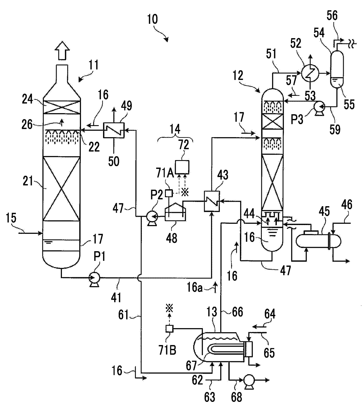
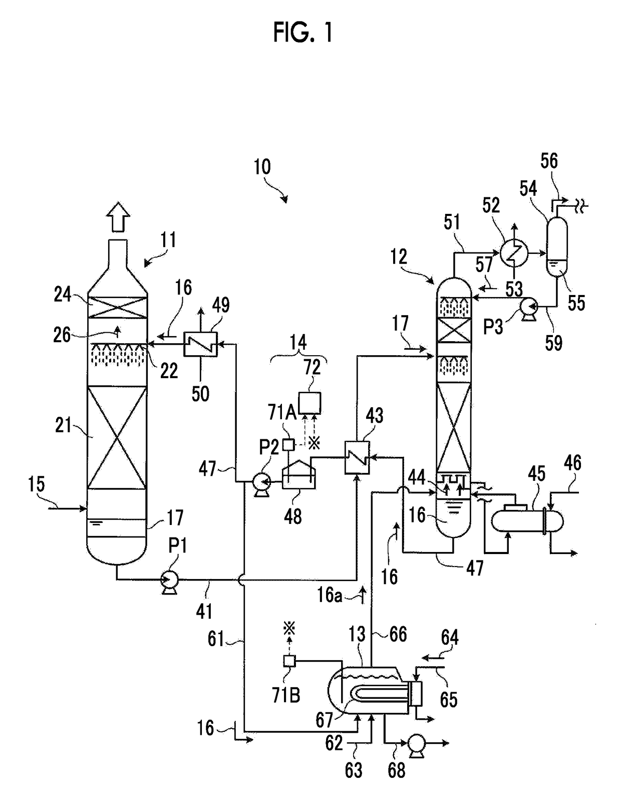
[0031]A degradant concentration measurement device according to a first embodiment of the invention will be described with reference to the accompanying drawings. FIG. 1 is a schematic view illustrating an acidic gas recovery device to which a degradant concentration measurement device according to a first embodiment of the invention is applied. As illustrated in FIG. 1, an acidic gas recovery device ...


PUM

PropertyMeasurementUnit
electric conductivityaaaaaaaaaa
temperatureaaaaaaaaaa
electric conductivity measurementaaaaaaaaaa

Abstract

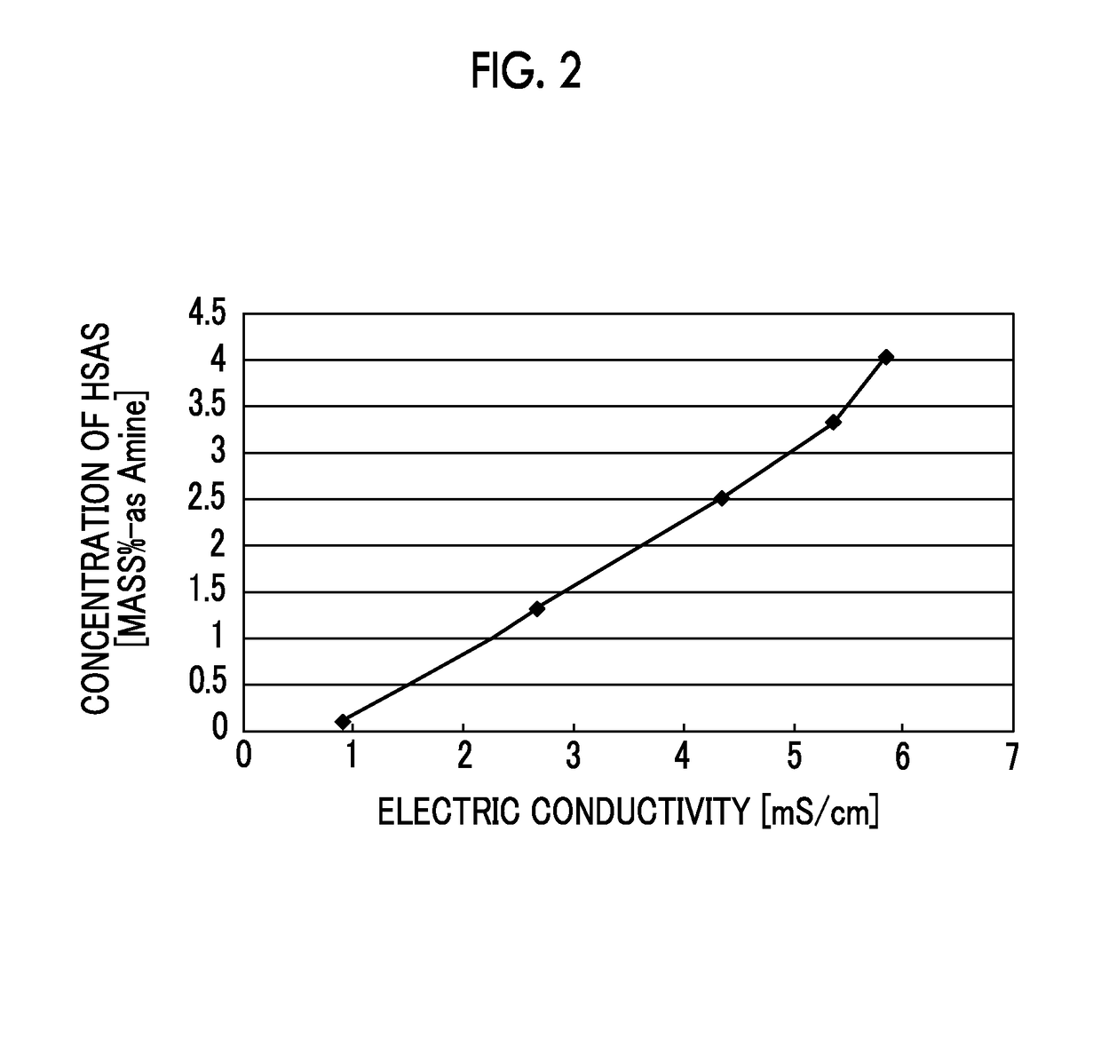
A degradant concentration measurement device 14 according to the invention has an electric conductivity measurement instrument 71A measuring the electric conductivity of a lean solution 16 that is an acidic gas-absorbing solution and detection means 72 obtaining the concentration of a degradant contained in a lean solution 16 from the measured electric conductivity of the lean solution 16 based on the relationship between the previously-obtained electric conductivity of the lean solution 16 and the concentration of the degradant contained in the lean solution 16.

Description

TECHNICAL FIELD[0001]The present invention relates to a degradant concentration measurement device and an acidic gas removal device that can be used to measure and manage a degradant contained in an absorbing solution used to remove acidic components (for example, carbon dioxide (CO2), hydrogen sulfide (H2S) and the like) contained in gas.BACKGROUND ART[0002]In a thermal power plant or the like in which a large amount of a fossil fuel is used, exhaust gas generated due to the combustion of a fossil fuel in a boiler, coal gasified gas (gasified gas) obtained by gasifying coal, and natural gas contain acidic gas components (for example, H2S, CO2 and the like). Gas containing the above-described acidic components is brought into gas-liquid contact with an amine-based acidic gas-absorbing solution in an absorption tower so that acidic gas is absorbed in the acidic gas-absorbing solution, whereby the acidic gas in the gas is removed and recovered.[0003]For example, a method is used in wh...

Claims


Application Information

Patent Timeline
Patent Type & Authority Patents(United States)
IPC IPC(8): B01D53/34C10K1/00B01D53/14G01N27/06G01N27/02G01N33/00B01D53/82C10K1/10C10L3/10
CPCB01D53/346B01D53/1475B01D53/82C10K1/003C10K1/10G01N27/02G01N27/06G01N33/0027B01D53/1425Y02P20/152B01D2252/20478B01D2258/0283C10L3/102C10L2290/541C10L2290/60Y02C10/06Y02C20/40Y02P20/151B01D53/14B01D53/52B01D53/62B01D53/77C10K1/14C10L3/10
Inventor YUKUMOTO, ATSUHIROHORIZOE, KOUJIKATO, YUDAIHIRAYAMA, HARUAKIISHIDA, KAZUO
Owner MITSUBISHI HEAVY IND ENG LTD
Learn More