Optical coherence tomography for biological imaging

a biological imaging and optical coherence tomography technology, applied in the field of optical coherence tomography for biological imaging, can solve the problems of refractive index, mismatching of refractive index, refractive index, etc., and achieve the effect of improving long- and short-term outcomes and reducing procedure tim

Active Publication Date: 2017-10-17
AVINGER
View PDF467 Cites 30 Cited by
  • Summary
  • Abstract
  • Description
  • Claims
  • Application Information

AI Technical Summary

Benefits of technology

[0013]Described herein are OCT catheter, catheter systems, and methods of using and manufacturing them. In general, the OCT catheters and systems described herein are appropriate for use in a patient in order to visualize the internal structures within a lumen of the body in real time. These systems may allow control and navigation of the catheter, including navigation around and through complex anatomy such as bifurcations, ostials, regions of tortuosity, and the like. Further, the real-time and efficient imaging, as well as the control of the imaging system may allow a reduction in procedure time and improvements for long- and short-term outcomes.
[0049]The embodiments described herein may have one or more of the following advantages.
[0050]Using an OCT system with a common path optical fiber and an interface medium having indexes of refraction that are mismatched allows the OCT receiving electronics to operate in a total noise range that is within 5 dB of the shot noise limit. Operating within 5 dB of the shot noise limit advantageously ensures that noise in the receiving electronics is low. Keeping noise in the receiving electronics low results in a higher quality image. When used with an atherectomy catheter, for example, higher quality images advantageously allow for better identification of target tissue.
[0051]Using swept source optical radiation and a common path optical fiber as part of an OCT system allows for the use of a significantly simplified optical system compared to standard time-domain OCT embodiments or swept-source embodiments using Michaelson or Mach-Zehnder interferometers. This allows for the most efficient use of optical radiation, which in turn permits well optimized detection of signal and commensurately higher image quality.
[0052]Embedding a silicon die having a reflective coating in an interface medium provides a high reflectivity surface for reflection of light from the fiber to the tissue and back from the tissue into the fiber. The high reflectivity surface ensures that a high percentage of light from the source of optical radiation will be reflected and returned from the tissue. Having more light reflected from the target improves the interference fringe contrast, resulting in a higher quality image.
[0053]A system for OCT that includes a common path optical fiber attached to a distal end of the catheter body and a handle attached to the proximal end of the elongate catheter body to rotate the catheter and the optical fiber allows the optical fiber to rotate with the catheter body without breaking or stretching. Allowing the optical fiber to rotate with the catheter body ensures that images can be taken at 360° angles about the catheter body. Taking images at 360° angles around the catheter body ensures that more tissue can be imaged. Moreover, including an optical fiber attached to a distal end of the catheter body and a handle attached to the proximal end of the elongate body to rotate the catheter and the optical fiber advantageously avoids having an additional bulky mechanism to rotate the fiber independently of the catheter.

Problems solved by technology

The first refractive index and the second refractive index can be mismatched such that the receiving electronics operate in a total noise range that is within 3 dB of the shot noise limit.
The first refractive index and the second refractive index can be mismatched such that the receiving electronics operate in a total noise range that is within 2 dB of the shot noise limit.

Method used


Image

  • Optical coherence tomography for biological imaging
  • Optical coherence tomography for biological imaging
  • Optical coherence tomography for biological imaging

Examples


example

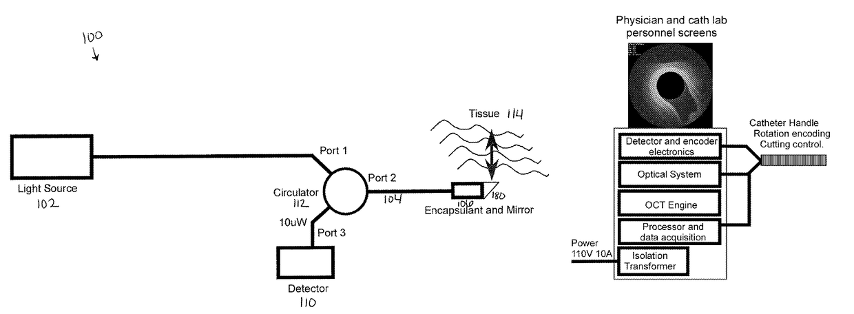
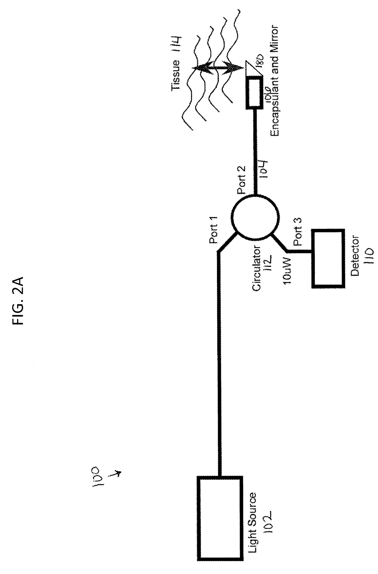
[0111]In one example, an image-guided interventional catheter (e.g., an OCT catheter as described above) may be used to address unmet needs in peripheral and coronary artery disease (atherosclerosis). The system may include a console having a modest footprint and in a cath lab without need for extensive integration into cath lab systems. In some variations, the systems described herein may be integrated with other catheter (e.g., guidance, control, imaging) systems. The system may be configured to allow a procedure to start / proceed / finish under fluoro guidance in the event of a system failure. The system is also configured to be compatible with sterile procedures.

[0112]As mentioned above, the OCT systems described herein may allow real-time information on intravascular lesion morphology and device orientation in the vessel. This and other features may also allow improved navigation precision around complex anatomy (e.g., bifurcations, ostials, tortuosity, cutting on a curve, etc.), ...


PUM


Abstract

Described herein are catheters for use with Optical Coherence Tomography (OCT) that include an optical fiber core having a first refractive index and an interface medium having a second refractive index, where the first and second refractive indexes are mismatched such that receiving electronics configured to receive optical radiation reflected from the reference interface and the target operate in a total noise range that is within 5dB of the shot noise limit. These OCT catheters may include a silicon die mirror having a reflective coating that is embedded in the interface medium. The optical fiber can be fixed at just the distal end of the catheter, and may be managed within a handle that is attached to the proximal end of the catheter body, and is configured to allow rotation of both the catheter body and the optical fiber relative to the handle.

Description

CROSS REFERENCE TO RELATED APPLICATIONS[0001]This application claims the benefit of U.S. Provisional Application No. 61 / 182,061, filed May 28, 2009, U.S. Provisional Application No. 61 / 258,064, filed Nov. 4, 2009, and U.S. Provisional Application No. 61 / 222,238, filed Jul. 1, 2009. The disclosures of these applications are incorporated herein by reference in their entirety.INCORPORATION BY REFERENCE[0002]All publications and patent applications mentioned in this specification are herein incorporated by reference in their entirety to the same extent as if each individual publication or patent application was specifically and individually indicated to be incorporated by reference.FIELD OF THE INVENTION[0003]Described herein are imaging devices and systems for use in biological probes. In particular, described herein are catheter-based imaging systems using Optical Coherence Tomography (OCT).BACKGROUND OF THE INVENTION[0004]In cardiovascular surgery, as well as other medical applicatio...

Claims


Application Information

Patent Timeline
Patent Type & Authority Patents(United States)
IPC IPC(8): A61B8/00A61B5/00
CPCA61B5/6852A61B5/0066
Inventor BLACK, JOHN F.SPENCER, MAEGAN K.ZUNG, MICHAELMCNALL, CHARLES W.LUMABAS, EVANGELINEROSENTHAL, MICHAEL H.SIMPSON, JOHN B.
Owner AVINGER
Why Eureka
Try Eureka