Rotary friction welding

a friction welding and friction welding technology, applied in the field of rotary friction welding process, can solve the problems of non-axisymmetric contact, variation in the conditioning duration, and upset of the welding process, so as to reduce the variability of the initial contact conditions at the weld surface, improve the defect expulsion effect, and reduce the upset variability

Active Publication Date: 2017-10-17
ROLLS ROYCE PLC
View PDF14 Cites 1 Cited by
  • Summary
  • Abstract
  • Description
  • Claims
  • Application Information

AI Technical Summary

Benefits of technology

[0018]Advantageously, by providing such an apex region, variability in the initial contact conditions at the weld surfaces can be reduced, leading to a more predictable conditioning period. As a result, upset variability can be reduced and defect expulsion improved. The process can thus be better optimised, for example allowing the amount of upset used to produce a given joint to be reduced, which can decrease material wastage through flash and / or decrease the amount of energy needed to produce the joint.
[0019]More particularly, the apex region can lead to a smaller variation in pressure between inner and outer sides of the tube wall. The pressure at the weld interface is thus more uniform. Further, local hotspots can be reduced or eliminated and less time may be required to form a plasticised interface zone. In addition, the sideways (i.e. radial) distance for defects to be rejected into flash can be reduced, and detrimental effects of workpiece diameter mismatch, eccentricity and lack of coaxiality can be reduced or eliminated. In addition, an increased pressure during contact can be achieved, thereby promoting an initial rapid expulsion of interface contaminants and improving sealing of the weld against re-introduction of contaminants.
[0027]The second weld surface may be a second apex region of a second annular projection at the end of the second workpiece, on a longitudinal section through the aligned workpieces the second annular projection having a profile in which radially inner and outer side surfaces of the second annular projection taper towards the second apex region. Optional features of the first annular projection can apply to the second annular projection. For example, the width of the second apex region on the longitudinal section may be at most 70% and / or at least 1 mm. The second apex region can be a flat surface or a convex surface. The side surfaces of the second annular projection may be angled by at least 5° to the radial direction and / or at most 20° to the radial direction. When the workpieces are formed of dissimilar materials, the shapes of the first and second apex regions can be adjusted accordingly. For example, a workpiece formed of softer material than the other workpiece may have larger side surface angles. In this way, due to the higher rate of upset of the softer workpiece, a better weld interface shape and position can be maintained.

Problems solved by technology

This is followed by upsetting when the temperature reaches a high enough level such that softening / melting of the workpiece material allows the workpieces to be pushed together, with liquid or quasi-liquid material being expelled sideways from a plasticised zone at the interface.
However, variations in contact conditions at the weld surfaces lead to variability in the welding process upset.
For example, due to machining tolerances, residual stress distortions etc., the weld surfaces are generally not completely flat, which leads to non-axisymmetric contact, producing local hotspots at the weld interface.
This results in variability in the efficiency of local heating during the conditioning period and hence variation in the conditioning duration.
In the fixed-energy inertia welding process this leads to variation in total upset and hence fitness for purpose either through reduced integrity at low upset (interface contaminants not fully expelled) or component fit at low or high upset.
Variations in contact conditions at the weld surfaces can also reduce control of defect expulsion.
For example, the material may be expelled non-axisymmetrically from the interfacial plasticised zone, with a result that interface contaminants may not be fully removed from all parts of the weld.
Accordingly, assumptions about flow and contaminant expulsion may be incorrect, leading to sub-optimal process and component design, or a low integrity product with a reduced life.
As well as non-flat weld surfaces, contact condition variability may also be produced by workpiece diameter mismatch, workpiece eccentricity and lack of workpiece coaxiality.
In addition, where a welding machine has a limited thrust capability this can compromise the preferred contact pressure for a given tubular wall thickness.
However, the workpieces may have more complex shapes.
On the other hand very narrow apex regions can be susceptible to sudden collapse / failure on engagement of the weld surfaces, and thus the width of the apex region on the longitudinal section may be at least 1 mm.

Method used


Image

  • Rotary friction welding
  • Rotary friction welding
  • Rotary friction welding

Examples


Embodiment Construction

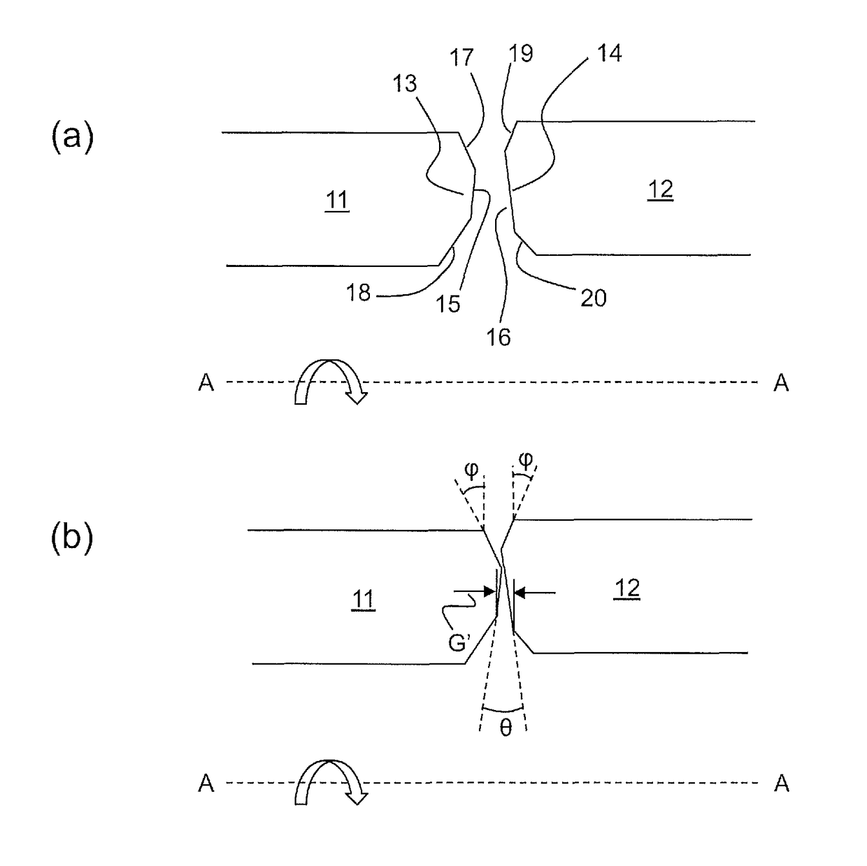
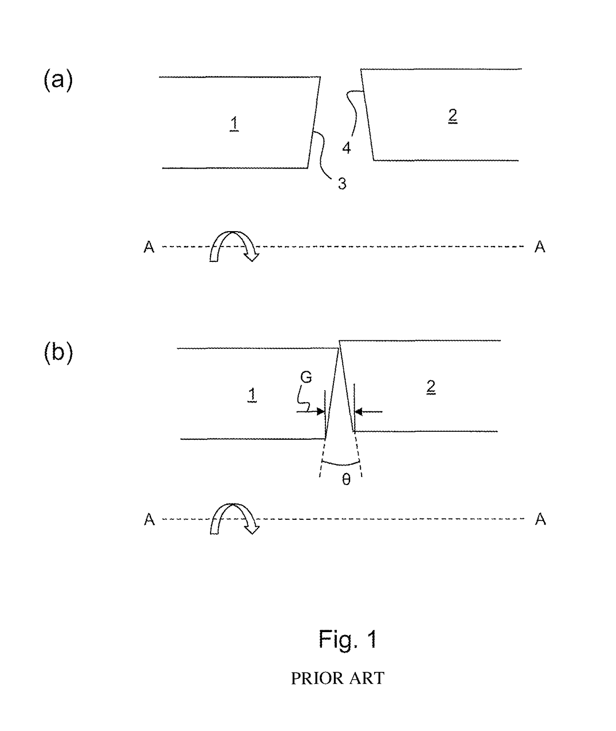
[0035]FIG. 1(a) shows schematically a longitudinal cross-section through a pair of conventional tubular workpieces 1, 2 in readiness to undergo rotary friction welding. The workpieces are aligned on a common axis A-A and have respective end faces forming weld surfaces 3, 4.

[0036]The left hand workpiece 1 is attached to a flywheel or drive system which is rotated at a predetermined speed, indicated by the solid arrow.

[0037]As shown in FIG. 1(b), the workpieces are brought together so that the weld surfaces 3, 4 make contact. However, due to manufacturing tolerances, the weld surfaces are not completely flat, and also not perpendicular to the axis A-A. In addition, the workpieces exhibit a diameter mismatch, eccentricities and / or axis misalignment. Accordingly, the weld surfaces meet at an angle θ, and have an initial point of contact which is offset to the outer edge of the workpiece walls, producing a large gap G between the weld surfaces at their inner diameters. During the conditi...


PUM

PropertyMeasurementUnit
angleaaaaaaaaaa
widthaaaaaaaaaa
widthaaaaaaaaaa

Abstract

A method providing a first tubular workpiece having a first weld surface at an end thereof, and a second tubular workpiece having a second weld surface at an end thereof; aligning the workpieces on a common axis with the weld surfaces facing each other, rotating one workpiece about the axis relative to the other workpiece, and engaging the first and second weld surfaces such that the rotation raises the temperature at the weld surfaces to create a weld interface; and ceasing the rotation and allowing the weld interface to cool to weld the workpieces together at the interface. The first weld surface is an apex region of an annular projection at the end of the first workpiece, on a longitudinal section through the aligned workpieces the annular projection having a profile in which radially inner and outer side surfaces of the annular projection taper towards the apex region.

Description

CROSS-REFERENCE TO RELATED APPLICATIONS[0001]This application is based upon and claims the benefit of priority from British Patent Application Number 1413923.2 filed 6 Aug. 2014, the entire contents of which are incorporated by reference.BACKGROUND[0002]1. Field of the Disclosure[0003]The present disclosure relates to a rotary friction welding process.[0004]2. Description of the Related Art[0005]Rotary friction welding is the process for welding together two bodies or workpieces by converting mechanical energy to heat energy by the friction between the engaging weld surfaces of the two workpieces. The process involves effecting relative rotation between the two workpieces while the weld surfaces remain in engagement with each other.[0006]For example, in inertia friction welding one of two coaxial workpieces is attached to a flywheel, rotated to a predetermined speed and then driven against the second workpiece using thrust supplied by the welding machine. A fixed amount of stored en...

Claims


Application Information

Patent Timeline
Patent Type & Authority Patents(United States)
IPC IPC(8): B23K33/00F16L13/02B23K20/12B23K101/06
CPCF16L13/02B23K20/12B23K20/129B23K33/006B23K2201/06F16L13/0281B23K2101/06
Inventor BRAY, SIMON EDWARDWALPOLE, ANDREW ROBERT
Owner ROLLS ROYCE PLC
Why Eureka
Try Eureka