Magnetic material sputtering target and manufacturing method thereof

a technology of magnetized material and sputtering target, which is applied in the direction of basic electric elements, electrical equipment, metal material coating process, etc., can solve the problems of oxides becoming a cause of abnormal electric discharge and particle generation,

Active Publication Date: 2017-10-17
JX NIPPON MINING & METALS CORP
View PDF32 Cites 1 Cited by
  • Summary
  • Abstract
  • Description
  • Claims
  • Application Information

AI Technical Summary

Benefits of technology

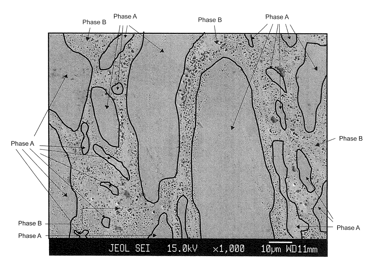
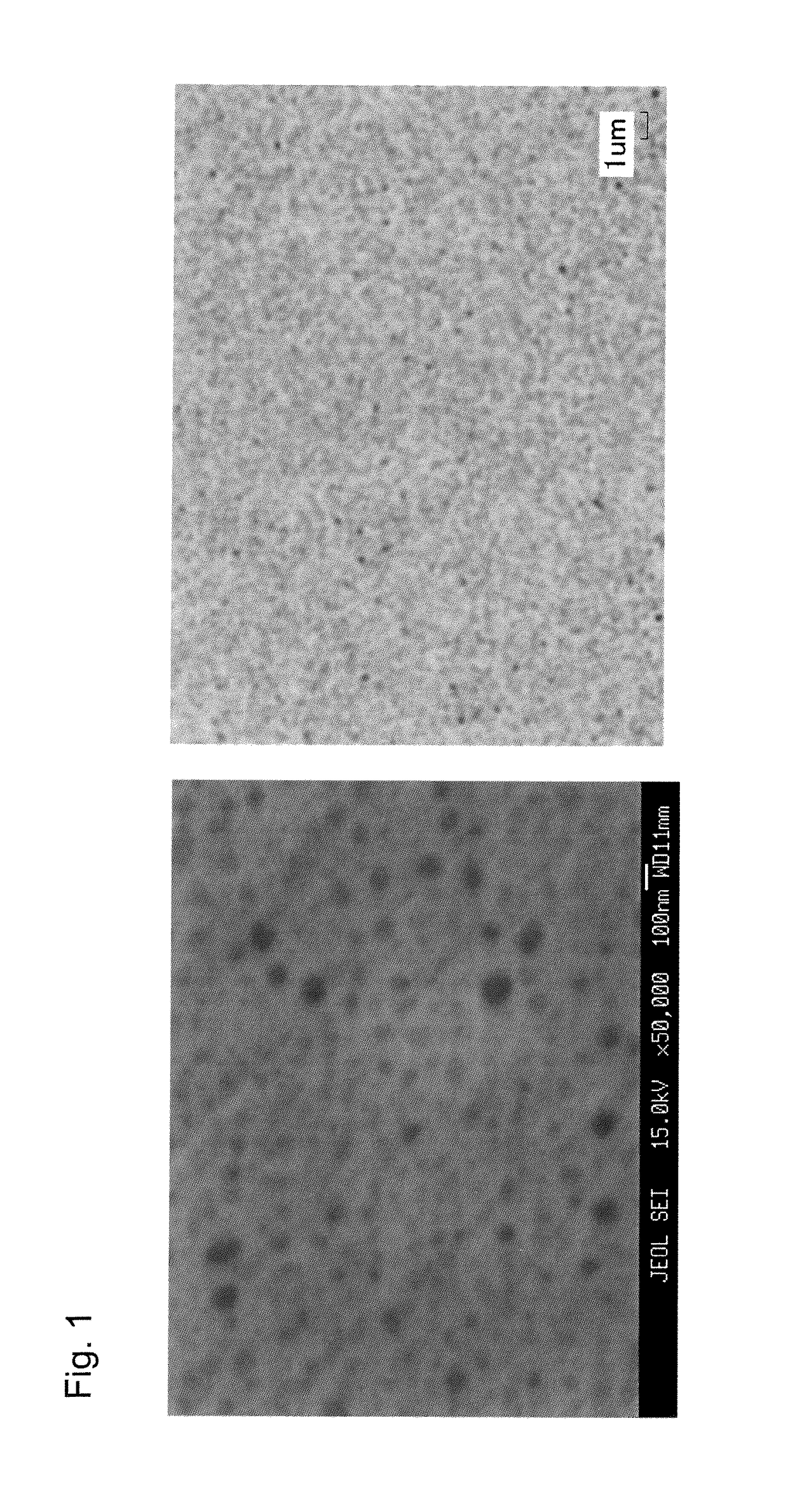
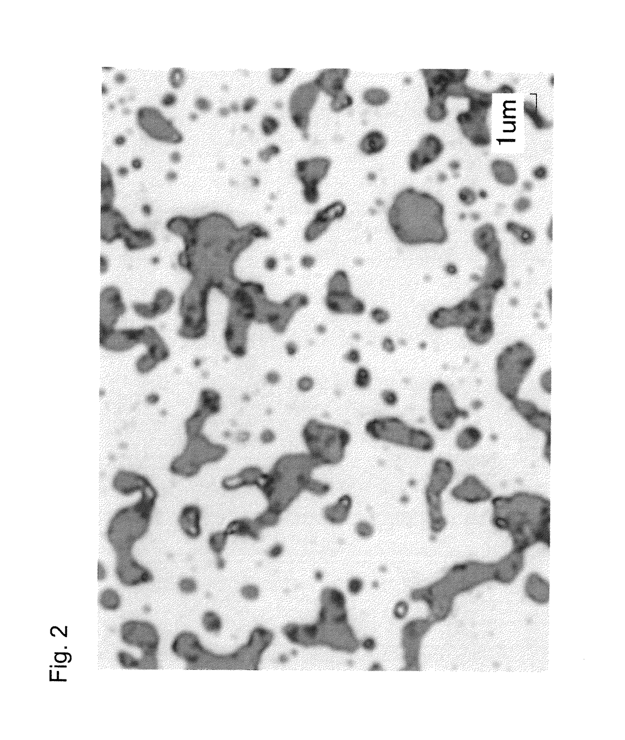
[0067]According to the present invention, the structure of a ferromagnetic sputtering target, in particular the shape of oxide grains can be adjusted (micronized) to reduce contamination of impurities from a grinding device and a medium. Therefore, abnormal electric discharge due to oxides during sputtering will not occur, and particle generation can be reduced. Therefore, when the target of the present invention is used, stable electric discharge can be obtained during sputtering using magnetron sputtering equipment. Further, the following advantageous effects can be achieved: abnormal electric discharge due to oxides can be suppressed; particle generation during spattering caused by abnormal electric discharge can be reduced; and cost improvement can be achieved by improved yields.
can be achieved: abnormal electric discharge due to oxides can be suppressed; particle generation during spattering caused by abnormal electric discharge can be reduced; and cost improvement can be achieved by improved yields.

Problems solved by technology

In general, since nonmagnetic grain-dispersed ferromagnetic sputtering targets such as a Co—Cr—Pt oxide includes oxides therein such as SO2, Cr2O3, TiO2, Ta2O5, CoO, Co3O4 and B2O3 which are insulators, the oxides may become a cause for abnormal electric discharge.
Therefore, this abnormal electric discharge will pose a problem of particle generation during sputtering.

Method used


Image

  • Magnetic material sputtering target and manufacturing method thereof
  • Magnetic material sputtering target and manufacturing method thereof
  • Magnetic material sputtering target and manufacturing method thereof

Examples


example 1

[0100]A Co powder having an average grain diameter of 4 μm, a Cr powder having an average grain diameter of 5 μm and a Pt powder having an average grain diameter of 3 μm were prepared as metal raw powders, and a TiO2 powder having an average grain diameter of 1 μm, a SiO2 powder having an average grain diameter of 0.7 μm and a Cr2O3 powder having an average grain diameter of 1 μm were prepared as oxide powders. These powders were weighed at the following composition ratio to achieve 2000 g. The component composition is as follows.

[0101]Composition: 70Co-18Pt-3Cr-4SiO2-2TiO2-3Cr2O3 (mol %)

[0102]The weighed powders were sealed in a 10-litter ball mill pot along with tungsten alloy balls as grinding media, and rotated for 120 hours for mixing. The resulting mixture was filled in a carbon mold, and hot pressed in a vacuum atmosphere under the following conditions: a temperature of 1050° C., a retention time of 2 hours, and welding force of 30 MPa to obtain a sintered compact. The sinter...

example 2

[0115]A Co powder having an average grain diameter of 4 μm, a Cr powder having an average grain diameter of 5 μm, a Pt powder having an average grain diameter of 3 μm and a Ru powder having an average grain diameter of 5 μm were prepared as metal raw powders; and a TiO2 powder having an average grain diameter of 1 μm, a SiO2 powder having an average grain diameter of 0.7 μm and a CoO powder having an average grain diameter of 1 μm were prepared as oxide powders. The powders were weighed at the following composition ratio to achieve 2000 g. The component composition is as follows.

[0116]Composition: 59Co-20Pt-5Ru-3Cr-5SiO2-2TiO2-6CoO (mol %)

[0117]The weighed powders were sealed in a 10-litter ball mill pot along with zirconia balls as grinding media, and rotated for 120 hours for mixing. The resulting mixture was filled in a carbon mold, and hot pressed in a vacuum atmosphere under the following conditions: a temperature of 1050° C., a retention time of 2 hours, and welding force of 3...

example 3

[0132]A Co powder having an average grain diameter of 4 μm, a Cr powder having an average grain diameter of 5 μm and a Pt powder having an average grain diameter of 3 μm were prepared as metal raw powders, and a Ta2O5 powder having an average grain diameter of 1 μm and a SiO2 powder having an average grain diameter of 0.7 μm were prepared as oxide powders. The powders were weighed at the following composition ratio to achieve 2000 g. The component composition is as follows.

[0133]Composition: 76Co-12Pt-5Cr-5Ta2O5-2SiO2 (mol %)

[0134]The weighed powders were sealed in a 10-litter ball mill pot along with zirconia balls as grinding media, and rotated for 120 hours for mixing. The resulting mixture was filled in a carbon mold, and hot pressed in a vacuum atmosphere under the following conditions: a temperature of 1050° C., a retention time of 2 hours, and welding force of 30 MPa to obtain a sintered compact. The sintered compact was ground with a surface grinder to give a disk-shaped tar...


PUM

PropertyMeasurementUnit
diameteraaaaaaaaaa
diameteraaaaaaaaaa
grain diameteraaaaaaaaaa

Abstract

Provided is an oxide-containing magnetic material sputtering target wherein the oxides have an average grain diameter of 400 nm or less. Also provided is a method of producing an oxide-containing magnetic material sputtering target. The method involves depositing a magnetic material on a substrate by the PVD or CVD method, then removing the substrate from the deposited magnetic material, pulverizing the material to obtain a raw material for the target, and further sintering the raw material. An object of the present invention is to provide a magnetic material target, in particular a nonmagnetic grain-dispersed ferromagnetic sputtering target capable of suppressing discharge abnormalities of oxides that are the cause of particle generation during sputtering.

Description

BACKGROUND[0001]The present invention relates to a ferromagnetic sputtering target used for depositing a thin film in a magnetic recording medium, in particular depositing a granular film on a magnetic recording medium for a hard disk in which the perpendicular magnetic recording system is used. The present invention also relates to a nonmagnetic grain-dispersed ferromagnetic sputtering target capable of suppressing discharge abnormalities of oxides that are the cause of particle generation during sputtering and a producing method thereof.[0002]Although a wide variety of systems are available for a sputtering device, a magnetron sputtering device equipped with a DC power supply is widely used in view of high productivity to deposit the above magnetic recording films. The sputtering method refers to one in which a substrate serving as a positive electrode is placed facing a target which serves as a negative electrode, and high voltage is applied between the substrate and the target u...

Claims


Application Information

Patent Timeline
Patent Type & Authority Patents(United States)
IPC IPC(8): C23C14/00C22C1/10C22C32/00H01J37/34C04B35/645C22C38/00B22F3/15C22C33/02C22C19/07C23C14/34G11B5/851C22C27/04C22F1/10
CPCH01J37/3426B22F3/15C04B35/6455C22C1/10C22C19/07C22C32/0021C22C32/0026C22C33/0278C22C38/002C23C14/3414G11B5/851C22C27/04C22C2202/02C22F1/10C22C5/04C22C32/0005C23C14/3407
Inventor OGINO, SHIN-ICHINAKAMURA, YUICHIRO
Owner JX NIPPON MINING & METALS CORP
Why Eureka
Try Eureka