Object detection apparatus
a technology of object detection and object, which is applied in the field of object detection apparatus, can solve the problems that the replacement of the stereoscopic camera with the monocular camera cannot lead to proper detection of the object, and the accuracy of detecting the azimuth angle of the second object on the basis of the captured imag
- Summary
- Abstract
- Description
- Claims
- Application Information
AI Technical Summary
Benefits of technology
Problems solved by technology
Method used
Image
Examples
first embodiment
[0034](First Embodiment)
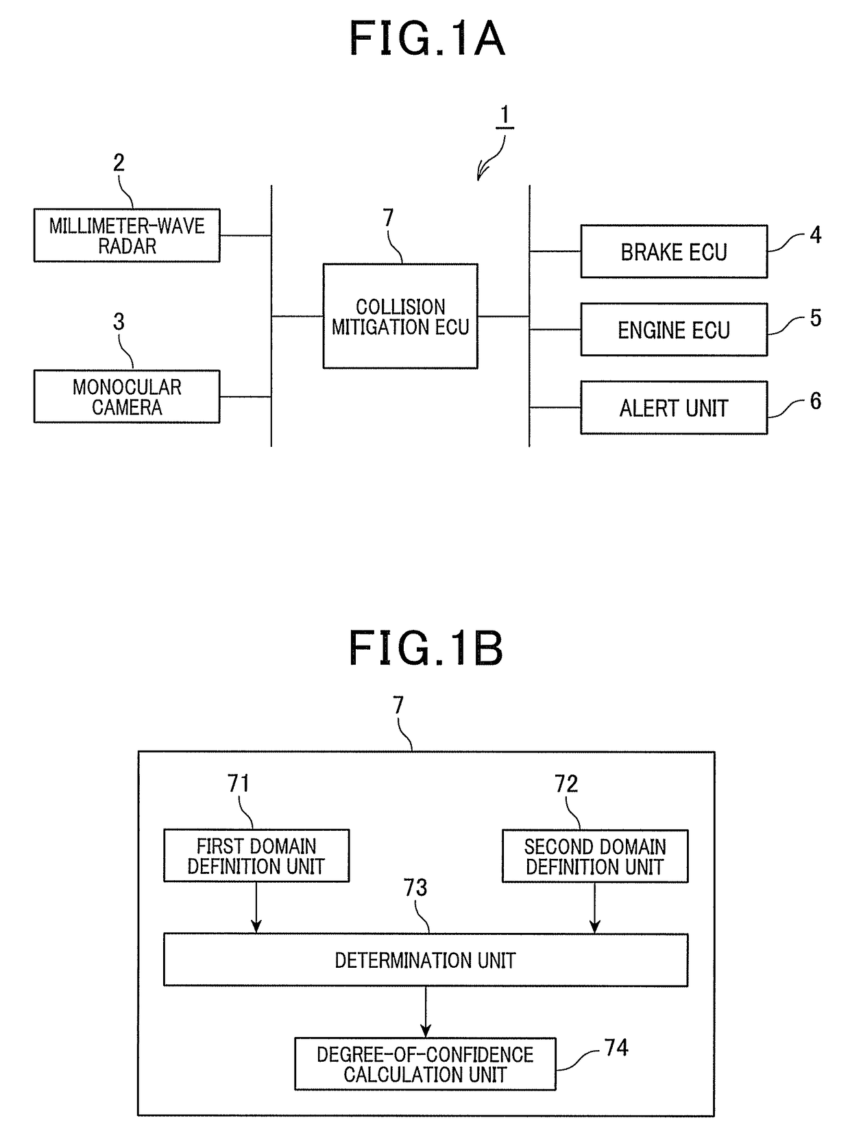
[0035]FIG. 1A shows a schematic diagram of a collision mitigation apparatus 1 in accordance of a first embodiment of the present invention. The collision mitigation apparatus 1 is mounted in a vehicle (hereinafter referred to as a subject vehicle), and includes a millimeter-wave radar 2, a monocular camera 3, a brake electronic control unit (ECU) 4, an engine ECU 5, an alert unit 6, and a collision mitigation ECU 7. In the collision mitigation apparatus 1, for example, the collision mitigation ECU 7 is communicably connected to the millimeter-wave radar 2, the monocular camera 3, the brake ECU 4, the engine ECU 5, and the alert unit 6.
[0036]The millimeter-wave radar 2 is mounted in the front middle portion of the subject vehicle to detect objects, such as other vehicles and pedestrians, by using millimeter waves. The millimeter-wave radar 2 transmits millimeter waves forward from the subject vehicle while scanning in a horizontal plane and receives millimeter...
second embodiment
[0074](Second Embodiment)
[0075]There will now be explained a second embodiment of the present invention. Only differences of the second embodiment from the first embodiment will be explained.
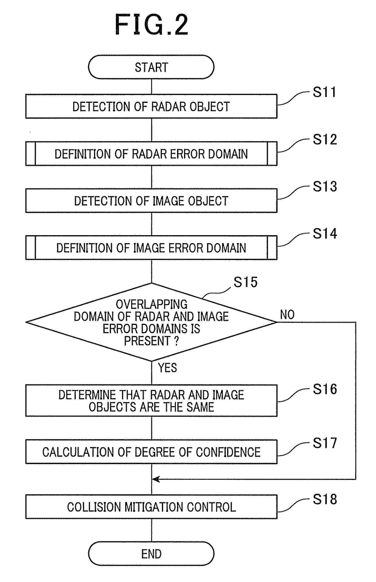
[0076]In the first embodiment described above, the radar error domain Rr is defined by an X-coordinate range of assumed error in the X-coordinate, centered at the X-coordinate of the detection point Pr, and a Y-coordinate range of assumed error in the Y-coordinate, centered at the Y-coordinate of the detection point Pr, where the assumed errors in the X- and Y-coordinates are predetermined on the basis of the characteristics of the millimeter-wave radar 2.
[0077]Alternatively, in the present embodiment, a radar error domain Rr is defined by a horizontal azimuth angle range of assumed error in the horizontal azimuth angle, centered at the horizontal azimuth angle of the detection point Pr, and a Y-coordinate range of assumed error in the Y-coordinate, centered at the Y-coordinate of the detection ...
third embodiment
[0080](Third Embodiment)
[0081]There will now be explained a third embodiment of the present invention. Only differences of the third embodiment from the second embodiment will be explained.
[0082]In the second embodiment, as described above, the radar error domain Rr and the image error domain Ri are defined in a similar manner to each other. As shown in FIG. 6, the radar error domain Rr is defined by a horizontal azimuth angle range of assumed error in the horizontal azimuth angle, centered at the horizontal azimuth angle of the detection point Pr, and a Y-coordinate range of assumed error in the Y-coordinate, centered at the Y-coordinate of the detection point Pr. Similarly, the image error domain Ri is defined by a horizontal azimuth angle range of assumed error in the horizontal azimuth angle, centered at the horizontal azimuth angle of the detection point Pi, and a Y-coordinate range of assumed error in the Y-coordinate, centered at the Y-coordinate of the detection point Pi.
[00...
PUM
 Abstract
Description
Claims
Application Information
 - R&D
- Intellectual Property
- Life Sciences
- Materials
- Tech Scout
- Unparalleled Data Quality
- Higher Quality Content
- 60% Fewer Hallucinations
Browse by: Latest US Patents, China's latest patents, Technical Efficacy Thesaurus, Application Domain, Technology Topic, Popular Technical Reports.
© 2025 PatSnap. All rights reserved.Legal|Privacy policy|Modern Slavery Act Transparency Statement|Sitemap|About US| Contact US: help@patsnap.com


