

Metal carbide fibers and methods for their manufacture
a technology of metal carbide fibers and fibers, which is applied in the chemical after-treatment of artificial filaments, fibre chemical features, textiles and paper, etc., can solve the problems that all other metal carbides are not currently available in fiber forms, and achieve high mechanical performance, high temperature resistance, and high temperature resistance.
- Summary
- Abstract
- Description
- Claims
- Application Information
AI Technical Summary
Benefits of technology
Problems solved by technology
Method used
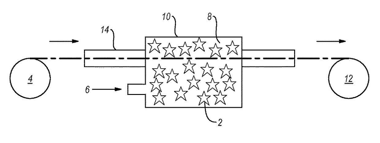
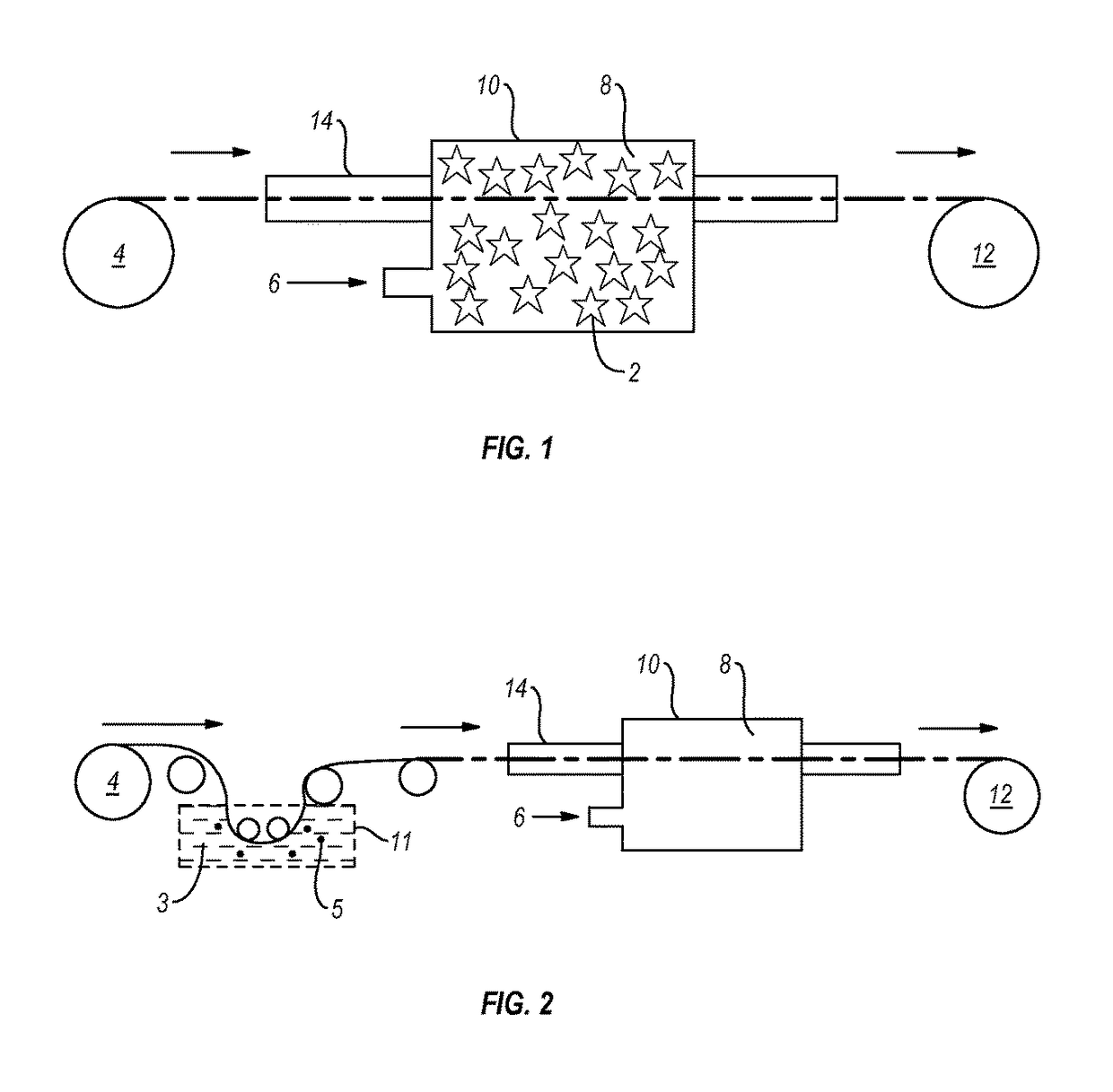
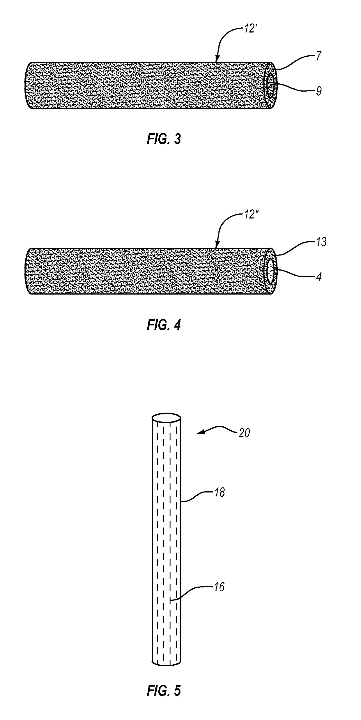
Image

Examples
Embodiment Construction
I. Introduction
[0037]Methods of forming at least one of calcium carbide or other metal carbide in fiber form are disclosed, as are metal carbide fibers. In addition, articles including the metal carbide fibers are disclosed. As used herein, the term “metal carbide” means and includes a chemical compound having at least one metal atom and at least one carbon atom, as indicated by the chemical formula MxCy, where x is 1 or 2, and y is 1, 2, or 3, or x and / or y are any of the values shown in Table 1. For convenience, the term “metal carbide” is used herein to collectively refer to calcium carbide, the rare earth carbides, and other carbides listed in Tables 1-2. The metal carbide may also be indicated herein by the terms “MC,”“MC2,”“M2C2,”“M2C3,”, etc. where M is the metal (calcium or rare earth, or other metal) cation. By way of example, the metal carbide may include, but is not limited to: aluminum carbide (Al4C3), beryllium carbide (Be2C), boron carbide (B4C to B12C), calcium carbid...
PUM
| Property | Measurement | Unit |
|---|---|---|
| diameter | aaaaa | aaaaa |
| diameter | aaaaa | aaaaa |
| thickness | aaaaa | aaaaa |
Abstract
Description
Claims
Application Information