
Adjustable coupling device and radio frequency communication device

a technology of a coupling device and a radio frequency communication device, which is applied in the field of communication technologies, can solve the problems of increasing the failure rate of the device, difficult to maintain a good working condition of the device, and difficulty in tuning, so as to achieve the effect of small influence on the output power, high cost and great isolation degr

Active Publication Date: 2017-11-14
ANHUI TATFOOK TECH CO LTD
View PDF9 Cites 0 Cited by
  • Summary
  • Abstract
  • Description
  • Claims
  • Application Information

AI Technical Summary

Benefits of technology

[0007]In view of the aforementioned deficiencies existing in the prior art, the present disclosure provides an adjustable coupling device and a radio frequency communication device, with simple structures. They eliminate the influence to the coupling device derived from the structure and the machining accuracy and assembly techniques of the printed circuit board, with easy tuning means and high reliability, and thus are favorable for mass production.
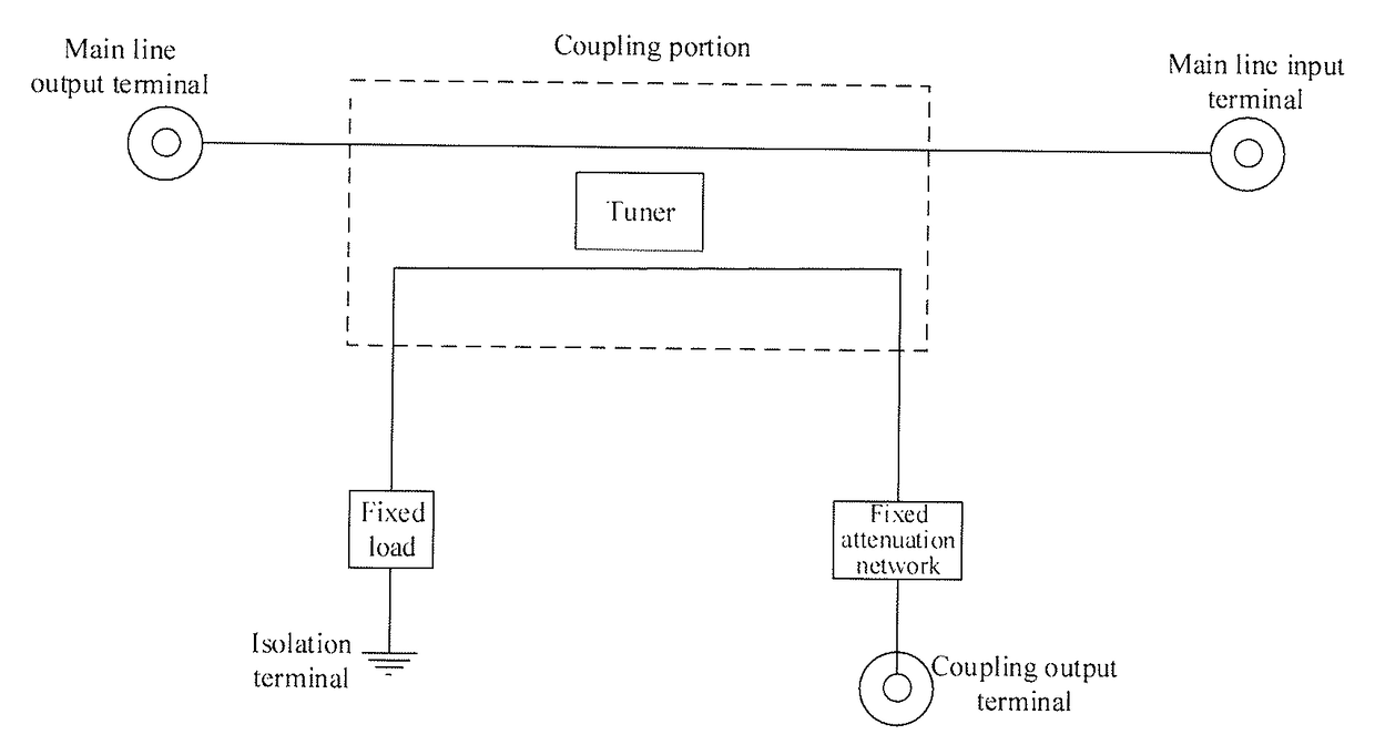
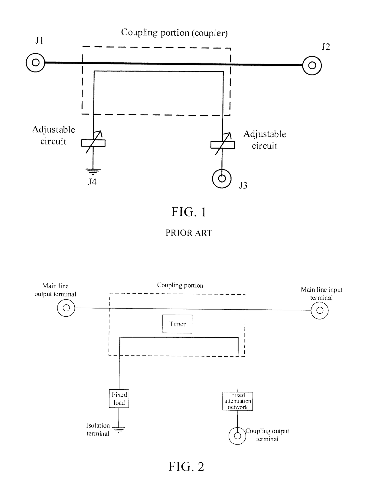
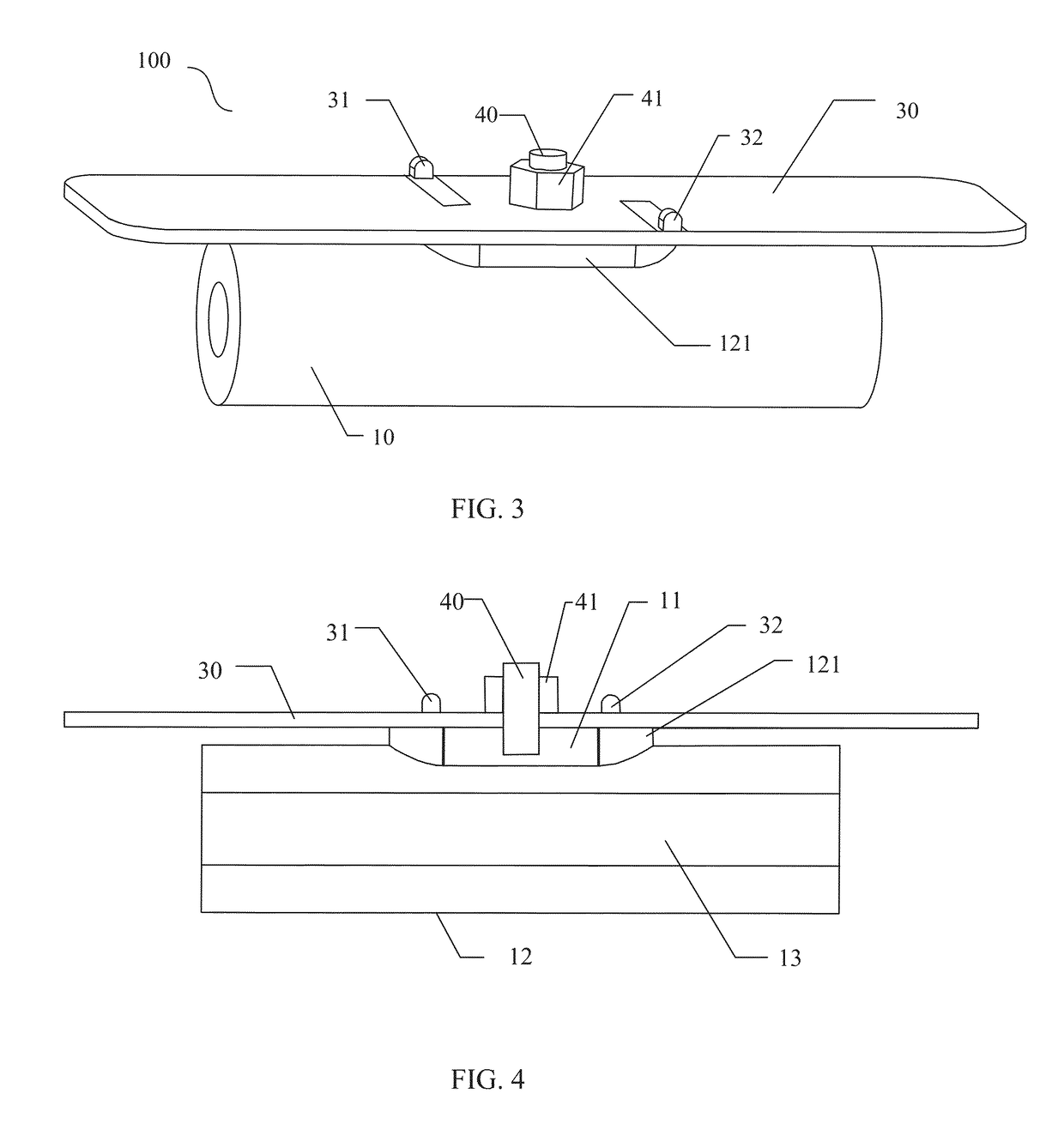
[0029]In the present disclosure, a coupling cavity is formed on the outer surface of the coaxial transmission line, a printed circuit board caps the coupling cavity, and a coupling body disposed on the printed circuit board is enclosed within the coupling cavity. A tuner extends through the printed circuit board into the coupling cavity, and can be moved up and down to change the depth thereof extended within the coupling cavity so as to change the electromagnetic field distribution within the coupling cavity, and thus further make the coupling amount and signal phase at different portions of the coupling body different. When the tuner is tuned to the optimal position, multiple signals coupled to the isolation terminal of the coupling body by the electric field within the coupling cavity cancel out each other's power, making the output power of signals at the isolation terminal reach the minimum (i.e., attaining the greatest isolation degree), while having an extremely small influence on the output power at the coupling output terminal. A fixed load (configured to absorb the remaining signal power and produce the impedance matching effects) will only be needed at the isolation terminal of the coupling device to meet the isolation requirements. Due to the extremely small influence on the coupling output terminal, the coupling adjustable circuit won't be needed. The present disclosure thus obviates the conventional complex coupling circuit with high cost, high failure rate and high level of manufacturing difficulty. A tuner causes perturbation of the internal field within the coupling cavity to adjust the indicators (for example, the directivity) of the coupling device, thus compensating for indicator deterioration derived from various machining errors.
[0030]In tuning, one only needs to change the depth of the tuner extended within the coupling cavity, while the position of the coupling body remains stationary, and connection relations between the coupling body and other circuits on the printed circuit board are stable, thereby further improving the reliability and thus achieving much simpler tuning means and coupling device structure. In this way, the present disclosure has a simple structure and thus eliminates the influence to the coupling device derived from the structure and the machining accuracy and assembly techniques of the printed circuit board, with simple tuning means and high reliability. Meanwhile, the present disclosure is more favorable for mass production.

Problems solved by technology

1. To achieve the required isolation specification and coupling specification, a coupling terminal adjustable circuit and an isolation terminal adjustable circuit would be needed. In actual tuning process, however, tuning the isolation terminal adjustable circuit will largely influence the coupling degree, while tuning the coupling terminal adjustable circuit will also influence the isolation degree, causing the tuning difficult.
2. With the increasement of the device's operating time, some adjusting components may be aging fast. The coupler may deteriorate dramatically in its performance, and even result in failure, causing communication failure of the device; components applied in the adjustable circuit may reduce the reliability of the device, thus increasing the failure rate of the device; components applied in the adjustable circuit may undergo wide parameters variation through high and low temperatures, thus making the communication device difficult to maintain a good working condition under various temperature environments; introduction of the adjustable circuit may lift up the raw material cost and production cost of the device.
However, the circuit on the printed circuit board that is connected to the coupling circuit board is fixedly arranged, thus, the connections between the coupling sheet and other circuits may be unstable when the coupling sheet rotates, and implementations of which may be relatively complex, resulting in poor reliability of the coupling device.

Method used


Image

  • Adjustable coupling device and radio frequency communication device
  • Adjustable coupling device and radio frequency communication device
  • Adjustable coupling device and radio frequency communication device

Examples


Embodiment Construction

[0045]Below a definite and complete description will be made on technical solutions of embodiments of the present disclosure with reference to the accompanying drawings corresponding to embodiments of the present disclosure. Apparently, the described embodiments are merely some but not all of the embodiments of the present disclosure. Based on embodiments of the present disclosure, all other embodiments obtained by those of ordinary skill in the art without making inventive effort shall fall within the protection scope of the present disclosure.

[0046]Working principles of the adjustable coupling device of the present disclosure are as below: a coupling body is employed as a sub-line to couple the radio frequency signals transmitted from a main line, and a tuner is added to the coupling portion so as to tune the phase and strength of multiple signals coupled to the coupling body. At the isolation terminal, a fixed load is adopted to connect to the coupling body, while at the coupling...


PUM


Abstract

The present disclosure relates to the field of communication technologies, and more particularly, to an adjustable coupling device and a radio frequency communication device. The adjustable coupling device includes a coaxial transmission line for transmitting signals across the two terminals thereof and a coupling body for sampling the signals via coupling. The adjustable coupling device further includes a coupling cavity formed on the outer surface of the coaxial transmission line; a printed circuit board on which the coupling body is disposed, the printed circuit board capping the coupling cavity to seal the coupling body within the coupling cavity; a tuner, disposed through the printed circuit board, where the lower end of the tuner extends into the coupling cavity, and the tuner can be moved up and down to change the depth thereof extended into the coupling body so as to change the electromagnetic field distribution within the coupling cavity. In this way, the present disclosure has a simple structure and thus eliminates the influence on the coupling device derived from the structure and the machining accuracy and assembly techniques of printed circuit board, with simple tuning means and high reliability.

Description

RELATED APPLICATION[0001]This application is a national phase entry under 35 USC 371 of International Patent Application No PCT / CN2013 / 087246 filed on 15 Nov. 2013, which claims priority from Chinese Patent Application No 201220609677.1 filed on 16 Nov. 2012, the disclosures of which are incorporated in their entirety by reference herein.FIELD OF THE DISCLOSURE[0002]The present disclosure relates to the field of communication technologies, and more specifically, to an adjustable coupling device and a radio frequency communication device.BACKGROUND OF THE DISCLOSURE[0003]In a base station, a radio remote unit (RRU), a standing wave detection system and a feed system, a coupling device is generally used to check the signal power. Circuitry of an existing coupling device is shown as in FIG. 1, where J2 and J1 are respectively an input terminal and an output terminal for main signals, J3 an output terminal for coupling signals, J4 an isolation terminal, and Coupler the coupling portion ...

Claims


Application Information

Patent Timeline
Patent Type & Authority Patents(United States)
IPC IPC(8): H01P3/08H01P5/04H01P5/08
CPCH01P5/04H01P5/085H01P3/081
Inventor WANG, HONGWEIXU, XIAOLIANGHUANG, XINCAIWU, WENJING
Owner ANHUI TATFOOK TECH CO LTD
Learn More