
In situ system and method of manufacturing nanoparticles having core-shell structure

a nanoparticle and core shell technology, applied in chemical/physical/physical-chemical processes, coatings, chemistry apparatuses and processes, etc., can solve the problems of increasing particle size, and irregular size of generated nanoparticles

Active Publication Date: 2017-11-21
DAEJIN UNIV CENT FOR EDUCATIONAL INDAL COOPERATION
View PDF8 Cites 1 Cited by
  • Summary
  • Abstract
  • Description
  • Claims
  • Application Information

AI Technical Summary

Benefits of technology

[0014]The present invention is also directed to provide an in situ system and method of manufacturing nanoparticles having a core-shell structure that are capable of easily adjusting a thickness of a shell material coated on the nanoparticles.
[0017]Further, a plurality of speed adjustment members may be installed in a longitudinal direction of the process passage at predetermined intervals, and the moving speed of the nanoparticles may be decreased due to flow resistance or collision when the nanoparticles pass through the speed adjustment member.
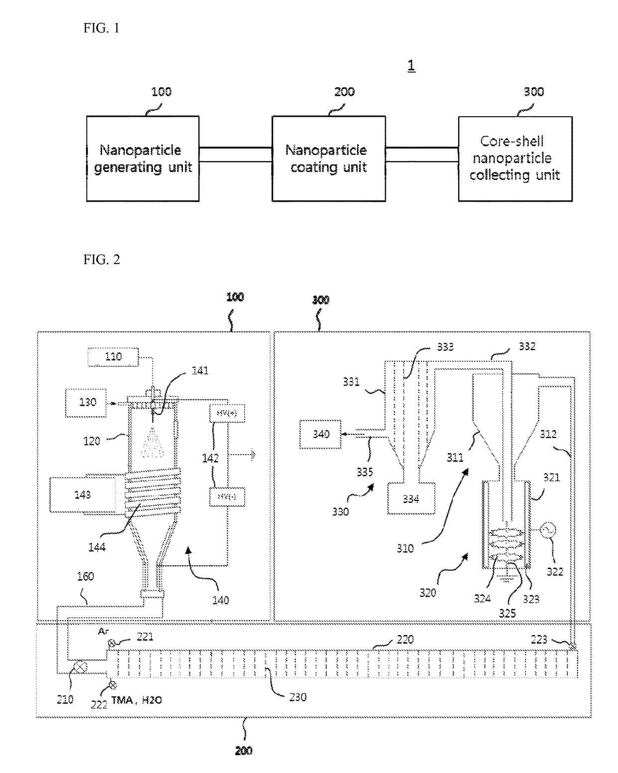
[0026]According to another aspect of the present invention, there is provided an in situ method of manufacturing nanoparticles having a core-shell structure, the method including: generating low pressure plasma in a reaction chamber, electrospraying a spray sample of nanoparticles into the reaction chamber, and supplying a carrier gas and a reactive gas to generate nanoparticles; supplying the nanoparticles and the carrier gas, and the reactive gas serving as a source of a shell material into a process passage of a coating chamber; coating the nanoparticles with the shell material by relatively rapidly moving the carrier gas supplied into the process passage and the reactive gas serving as the source of the shell material more than the nanoparticles as a moving speed of the nanoparticles supplied into the process passage of the coating chamber is decreased by a speed adjustment member; and collecting the nanoparticles having the core-shell structure coated with the shell material.

Problems solved by technology

However, the related art including the related documents has a problem that the sizes of the generated nanoparticles are irregular because the nanoparticles having the core-shell structure are still developed on a laboratory level, and the particle size is increased and becomes irregular because time elapses in a state in which the reaction on the surfaces of the generated nanoparticles is not completely terminated.

Method used


Image

  • In situ system and method of manufacturing nanoparticles having core-shell structure
  • In situ system and method of manufacturing nanoparticles having core-shell structure
  • In situ system and method of manufacturing nanoparticles having core-shell structure

Examples


Embodiment Construction

[0032]Hereinafter, an embodiment of the present invention will be described in detail with reference to the accompanying drawings.

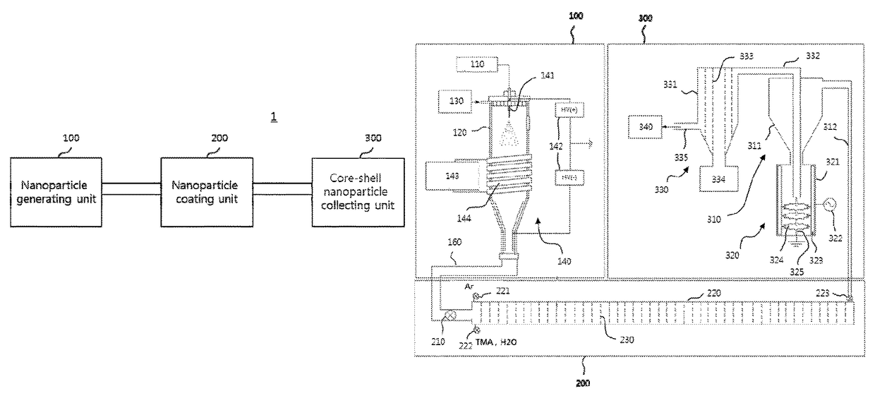
[0033]As shown in FIG. 1, an in situ system 1 for manufacturing nanoparticles having a core-shell structure according to an embodiment of the present invention includes a nanoparticle generating unit 100 configured to generate nanoparticles in a reaction chamber using low pressure plasma, a nanoparticle coating unit 200 configured to supply nanoparticles and a reactive gas serving as a source of a shell material into a coating chamber and coat the shell material on surfaces of the nanoparticles, and a core-shell nanoparticle collecting unit 300 configured to collect the nanoparticles having the core-shell structure coated with the shell material.

[0034]The nanoparticle generating unit 100, the nanoparticle coating unit 200, and the core-shell nanoparticle collecting unit 300 are connected to link processes and continuously process the processes. In the emb...


PUM

PropertyMeasurementUnit
core-shell structureaaaaaaaaaa
structureaaaaaaaaaa
moving speedaaaaaaaaaa

Abstract

Disclosed is a nanoparticle generating unit, a nanoparticle coating unit, and a core-shell nanoparticle collecting unit are connected to link and continuously process generation of nanoparticles and a coating and collecting process. The nanoparticle coating unit is formed of a porous material or in a grid structure and a moving speed of the nanoparticles can be decreased using a speed adjustment member installed at a process passage of a coating chamber.

Description

CROSS-REFERENCE TO RELATED APPLICATION[0001]This application claims priority to and the benefit of Korean Patent Application No. 2013-0110862, filed on Sep. 16, 2013, the disclosure of which is incorporated herein by reference in its entirety.BACKGROUND[0002]1. Field of the Invention[0003]The present invention relates to a nanoparticle manufacturing technology of a core-shell structure, and more particularly, to an in situ system and method of manufacturing nanoparticles having a core-shell structure capable of collecting nanoparticles coated with a shell material after a reactive gas supplied into a process passage of a coating chamber as a source of the shell material overtakes foregoing nanoparticles and is processed in a coating process through a multi-step collecting process at a high yield, and manufacturing high purity nanoparticles uniform and appropriate for mass production through continuous processing related to generation of nanoparticles and a coating and collecting pro...

Claims


Application Information

Patent Timeline
Patent Type & Authority Patents(United States)
IPC IPC(8): C23C16/54C23C16/455C23C16/56C23C16/40C23C16/44B82Y40/00
CPCC23C16/45555B82Y40/00C23C16/4417C23C16/54C23C16/403C23C16/56B01J19/00B82B3/00
Inventor PARK, SUNGHOCHAE, WON-SEOKHAN, MAN SO
Owner DAEJIN UNIV CENT FOR EDUCATIONAL INDAL COOPERATION
Learn More