Hydroseeder with pivoting auger conveyor

a technology of auger conveyor and hydraulic pump, which is applied in the direction of liquid seeding technique, sowing, agriculture, etc., can solve the problems of slipping and falling from a significant height, platform may be slippery, and the operator is at an elevated height prone to slip and fall dangers

Active Publication Date: 2017-12-05
THOMAS THOMAS M
View PDF31 Cites 7 Cited by
  • Summary
  • Abstract
  • Description
  • Claims
  • Application Information

AI Technical Summary

Problems solved by technology

The elevated height allows the operator to observe the spray operation but involves the risk of slipping and falling from a significant height.
The platform may be slippery due to overspray of the liquid slurry, due to wind, rain and snow, and due to water and particulate matter spillage during loading of the tank.
Spillage of dry particulate material from the bags creates a slip and fall danger for the operator at an elevated height.
Spillage of seeds, mulch and binder creates waste and increases cost.
Therefore the conventional hydroseeder equipment imposes significant safety risks to the operator including falls from a height, slipping on a wet platform surface, slipping on dry spilled particulate matter on the platform surface, and the risk of falling from the ladder used to access the elevated platform.
If the spray operator on the elevated platform chooses to spray while a driver moves the vehicle, an extremely unsafe condition arises, which likely violates various worker safety regulations but increases the speed of the spray operation.
The spray operator may slip on the platform surface during vehicle movement.
The spray operator may be knocked off balance by the movement of the vehicle or by the force of the pressurized liquid whipping the hose and nozzle.
If a fall occurs, the driver may not notice because of limited visibility and because of the noise created by the pump and vehicle engine.
However due to the nature of the hydroseeding work, operators may be working alone or in unpopulated areas where close supervision is impractical.
Material handling at a height involves risk of injury to the workers since bags of dry material are lifted to the elevated platform using forklifts or other equipment with imperfect visibility, and the bags are manually carried to the access hatch during loading of the mixing tank.
Conventional hydroseeder equipment with an elevated platform also requires inefficient and time consuming material handling of bags of dry particulate matter.
In any case the operator must climb a ladder to the elevated platform, work at an elevated height to handle the bags of materials and then climb down the ladder from the platform to drive in the vehicle, all of which consumes time and involves safety risk due to the platform height.

Method used


Image

  • Hydroseeder with pivoting auger conveyor
  • Hydroseeder with pivoting auger conveyor
  • Hydroseeder with pivoting auger conveyor

Examples


Embodiment Construction

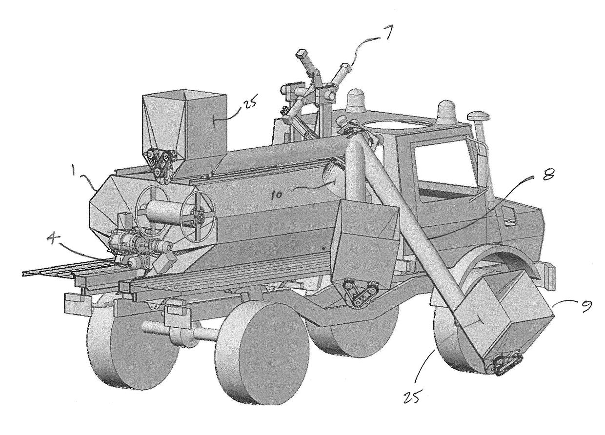
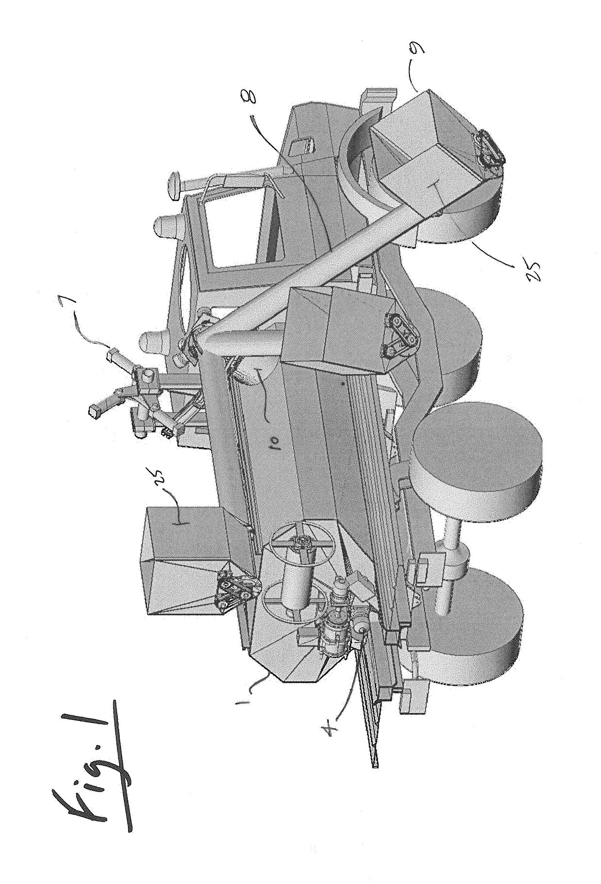
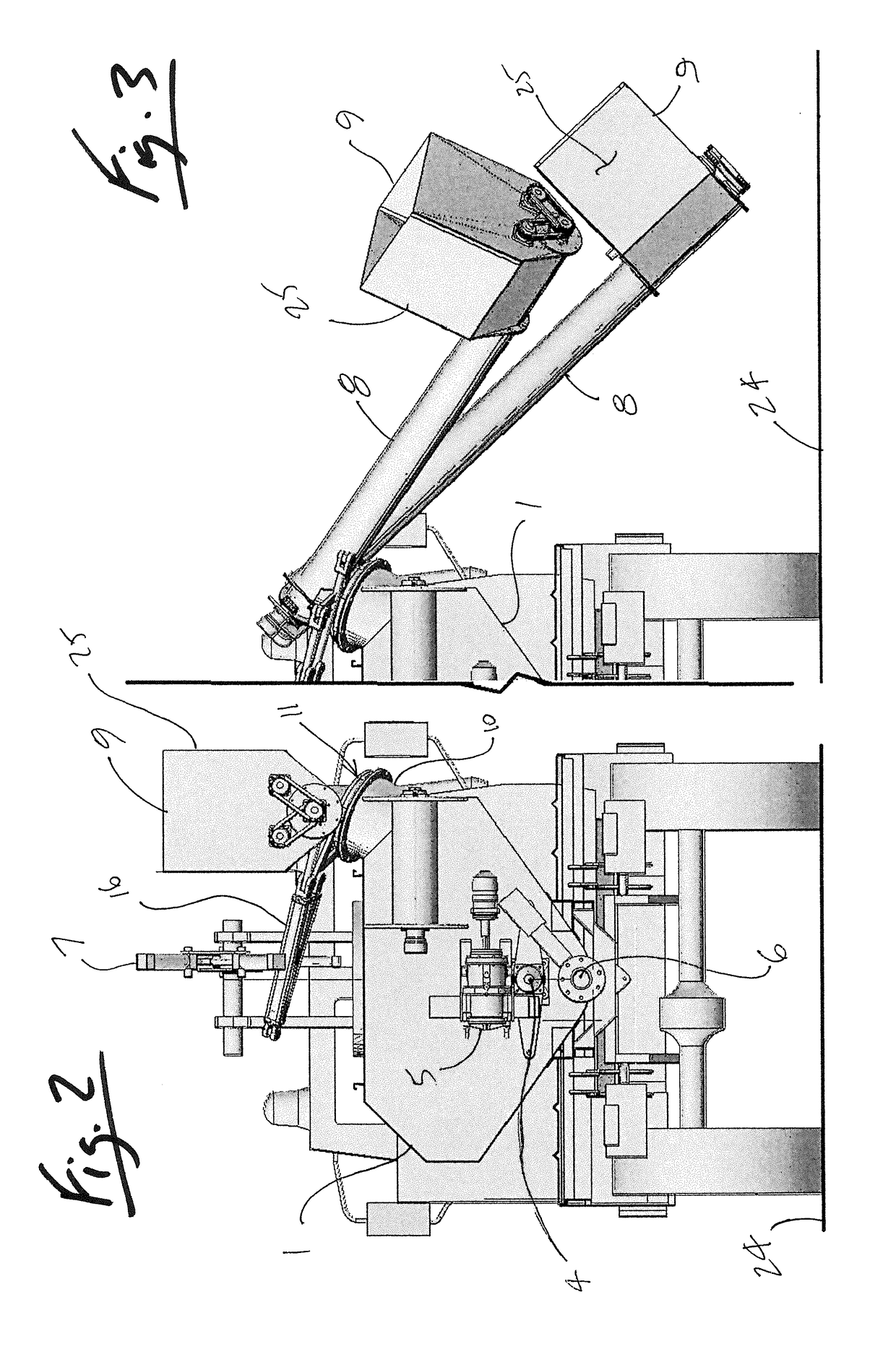
[0030]FIGS. 1 to 6 show various views of an example where the hydroseeder is mounted to a structural subframe hinged to the chassis beams of an automotive vehicle for spraying a slurry mixture of seed, mulch, binder and water on a ground surface. The vehicle has an engine that includes a power take-off shaft that can be used for driving a hydraulic pump and powering the hydraulic circuit. The hydroseeder can also be constructed with an independent engine or electric motor to power the hydraulic circuit. Various hydraulic cylinders and hydraulic motors can be operated using the hydraulic fluid power generated to rotate and actuate parts of the hydroseeder such as an internal mixer in the tank, slewing of the auger conveyor, deployment of the spray nozzle, driving of the water pump and tilting of the tank for drainage and cleaning.

[0031]The vehicle illustrated is a four-wheel drive truck having the advantage of being relatively small, maneuverable and lightweight for access over steep...


PUM


Abstract

A hydroseeder, for spraying a slurry mixture on a ground surface, the hydroseeder comprising: a liquid containment tank having an internal mixer, a tank inlet and a tank outlet, wherein the tank inlet is disposed above a maximum liquid fill level of the tank; a pump and a spray nozzle in communication with the tank outlet; a conveyor comprising an enclosed cantilever housing having an infeed chute at a lower end and a discharge spout at an upper end in communication with the tank inlet, the discharge spout of the enclosed cantilever housing pivotally supported on a slew ring to rotate about an axis of rotation relative to the tank inlet, the slew ring sealing between the discharge spout and the tank inlet during rotation between a stowed position and a deployed position; wherein the infeed chute in the deployed position is disposed at a loading height from the ground surface.

Description

TECHNICAL FIELD[0001]The invention relates to a hydroseeder having a mixing tank, pump and nozzle for spraying a slurry of water, seed and mulch on soil surfaces, where the mixing tank is loaded using a pivoting auger conveyor.BACKGROUND OF THE ART[0002]Hydroseeding is a process for planting seeds of grass or plants on a soil surface where a mixing tank, pump and nozzle are used to spray a slurry mixture of water, seed, mulch and a bio degradable adhesive type binder on the soil surface. The binder and mulch retain moisture, resist soil erosion and physically restrain the seeds from moving during germination and root growth. The binder and mulch eventually decay while the seed grows into rooted plants.[0003]Conventional hydroseeders are often mounted to vehicles and include a mixing tank with a platform on the top surface of the tank. The platform provides the operator with access to a hatch into which water, bags of dry seed, mulch and binder are loaded into the tank. Tanks include...

Claims


Application Information

Patent Timeline
Patent Type & Authority Patents(United States)
IPC IPC(8): A01C7/00A01C15/00
CPCA01C15/003A01C7/004
Inventor THOMAS, THOMAS M.
Owner THOMAS THOMAS M
Why Eureka
Try Eureka