Compressor flow path

a compressor and flow path technology, applied in the field of compressors, can solve the problems of increasing the overall size of the compressor, and achieve the effect of reducing flow losses and simplifying the assembly of the produ

Active Publication Date: 2017-12-26
DYSON TECH LTD
View PDF9 Cites 30 Cited by
  • Summary
  • Abstract
  • Description
  • Claims
  • Application Information

AI Technical Summary

Benefits of technology

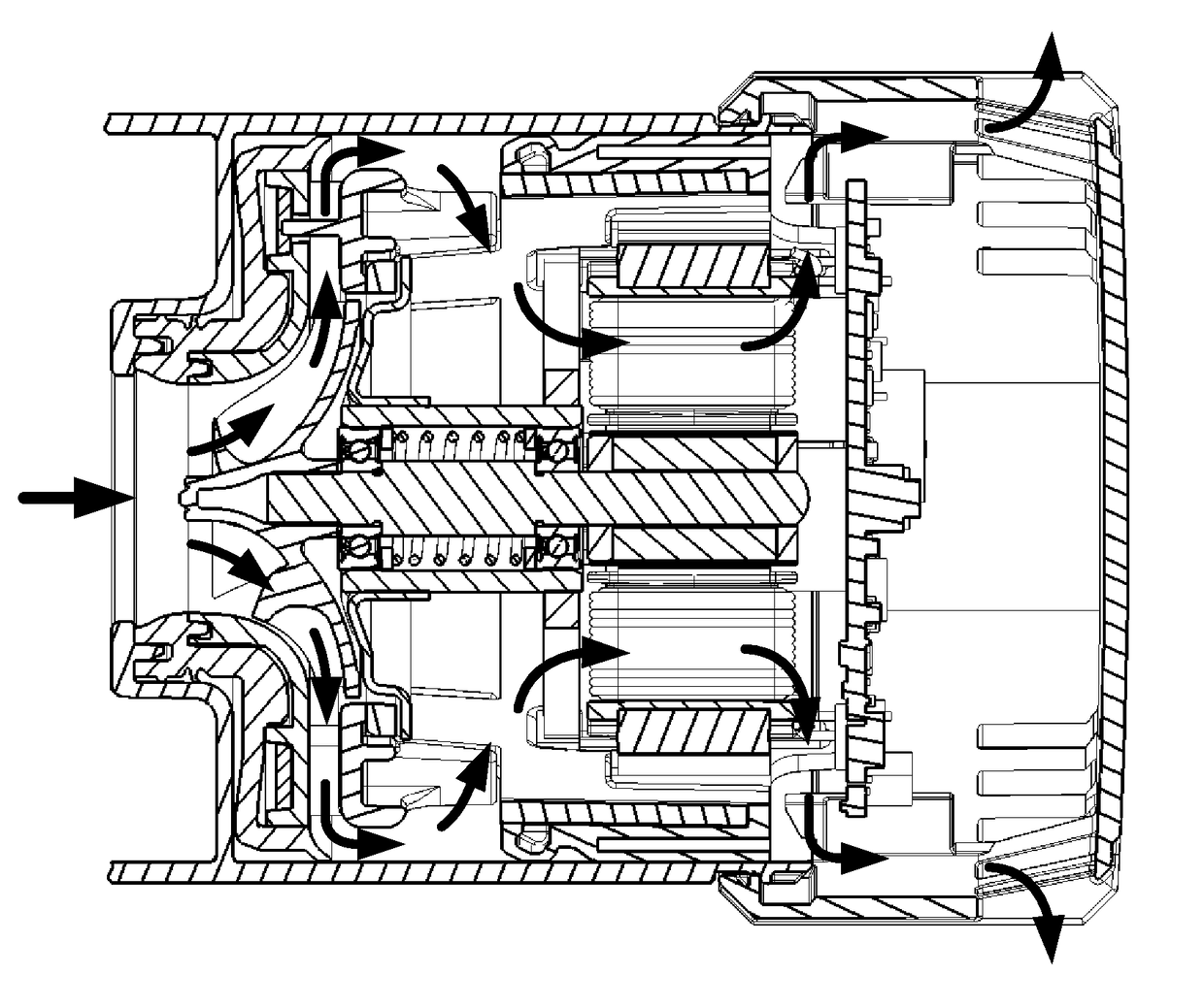
[0005]Rather than using the casing of the compressor, the present invention instead uses the housing and the mount to return fluid back into the interior of the compressor. As a result, a more compact arrangement may be achieved.
[0016]The mount or further mount may turn the fluid exiting the first outlet in a direction towards the second inlet. In particular, the mount or further mount may include a curved surface for turning the fluid. As a result, the fluid follows a smoother path between the first outlet and the second inlet, thus reducing flow losses.

Problems solved by technology

However, this then increases the overall size of the compressor.

Method used


Image

  • Compressor flow path
  • Compressor flow path
  • Compressor flow path

Examples


Embodiment Construction

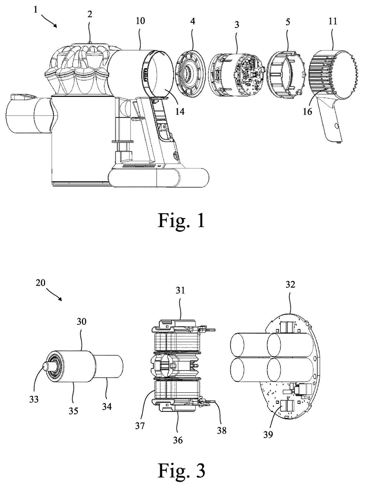
[0025]The product 1 of FIG. 1 comprises a housing 2, a compressor 3, an axial mount 4 and a radial mount 5. Each of the mounts 4,5 is located between the housing 2 and the compressor 3 and acts to isolate the housing 2 from vibration generated by the compressor 3. In this particular example, the product 1 is a handheld vacuum cleaner.

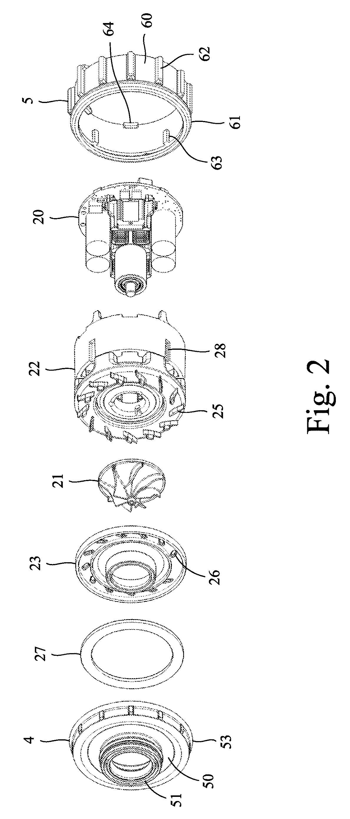
[0026]Referring now to FIGS. 2 and 3, the compressor 3 comprises an electric motor 20, an impeller 21, a frame 22 and a shroud 23.

[0027]The motor 20 comprises a rotor assembly 30, a stator assembly 31 and a circuit assembly 32. The rotor assembly 30 comprises a shaft 34 to which a rotor core 35 and a bearing assembly 36 are attached. The stator assembly 31 comprises a pair of stator cores 37 around which electrical windings 38 are wound. The windings 38 are connected to the circuit assembly 32 via terminal connectors, which also act to secure the circuit assembly 32 to the stator assembly 31. The rotor assembly 30 and the stator assembly 31 are each sec...


PUM


Abstract

A product that includes a compressor, a housing and a vibration isolation mount located between the compressor and the housing. The compressor includes an impeller, a first inlet located upstream of the impeller, a first outlet located downstream of the impeller, a second inlet located downstream of the first outlet, and a second outlet located downstream of the second inlet. During operation, fluid enters the compressor via the first inlet and exits the compressor via the first outlet. The mount creates a restriction between the compressor and the housing that causes fluid exiting the first outlet to re-enter the compressor via the second inlet.

Description

REFERENCE TO RELATED APPLICATION[0001]This application claims priority of United Kingdom Application No. 1308090.8, filed May 3, 2013, the entire contents of which are incorporated herein by reference.FIELD OF THE INVENTION[0002]The present invention relates to a compressor and the path taken by fluid flowing through the compressor.BACKGROUND OF THE INVENTION[0003]The casing of a compressor may be configured such that fluid exiting the impeller is returned through the interior of the compressor so as to cool components of the compressor. However, this then increases the overall size of the compressor.SUMMARY OF THE INVENTION[0004]The present invention provides a product comprising a compressor, a housing, and a vibration isolation mount located between the compressor and the housing, wherein the compressor comprises an impeller, a first inlet located upstream of the impeller, a first outlet located downstream of the impeller, a second inlet located downstream of the first outlet, an...

Claims


Application Information

Patent Timeline
Patent Type & Authority Patents(United States)
IPC IPC(8): A47L5/22F04D29/66A47L9/00F04D29/16F04D29/58H02K5/24F04D25/08A47L9/22H02K1/18H02K9/06F04D17/16F04D29/44A47L5/24H02K11/33
CPCA47L5/24A47L9/0081A47L9/22F04D17/16F04D25/082F04D29/162H02K11/33F04D29/5806F04D29/668H02K1/185H02K5/24H02K9/06F04D29/441
Inventor HILL, ROBERT STANLEYCLOTHIER, ANDREW CHARLTON
Owner DYSON TECH LTD
Why Eureka
Try Eureka