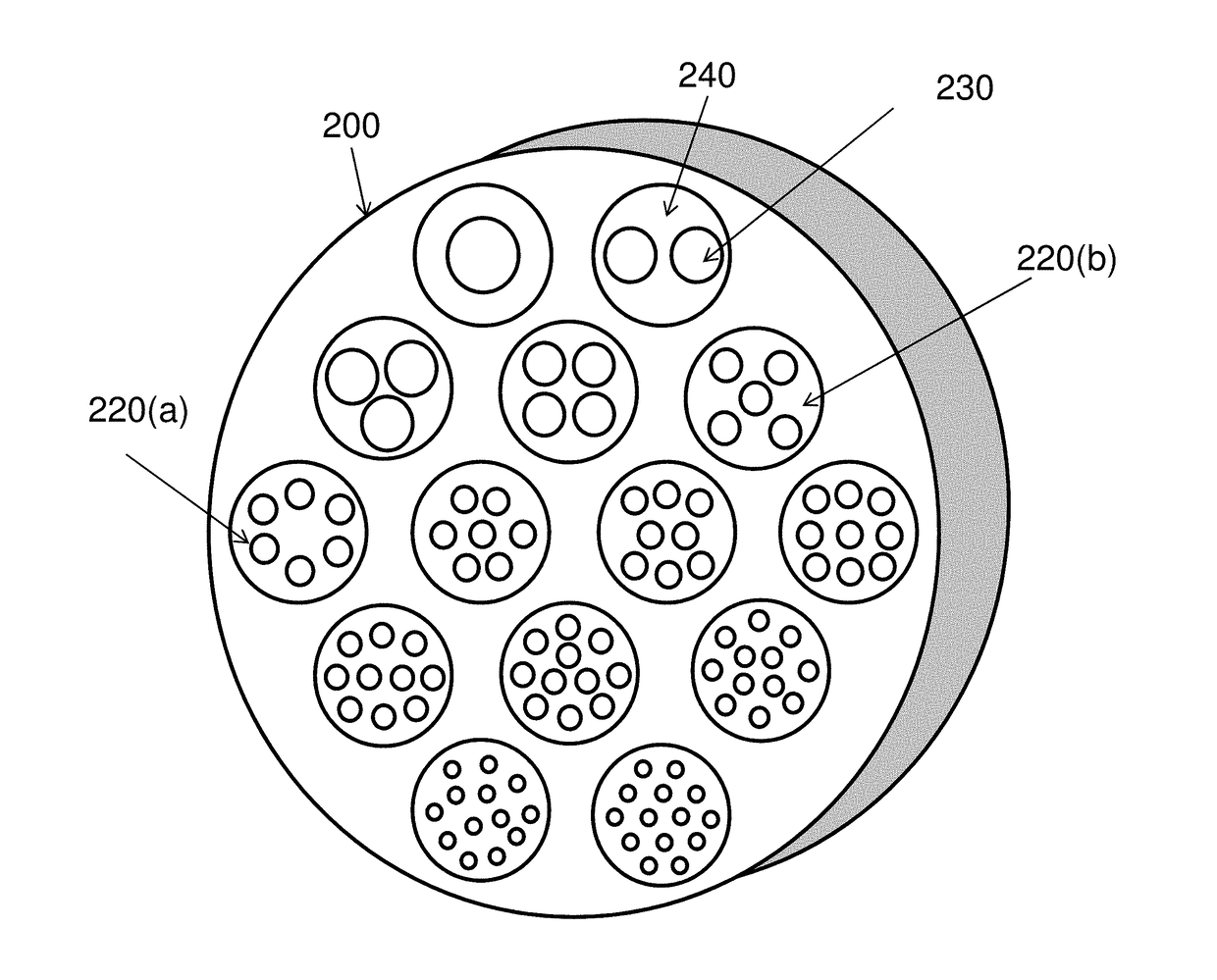
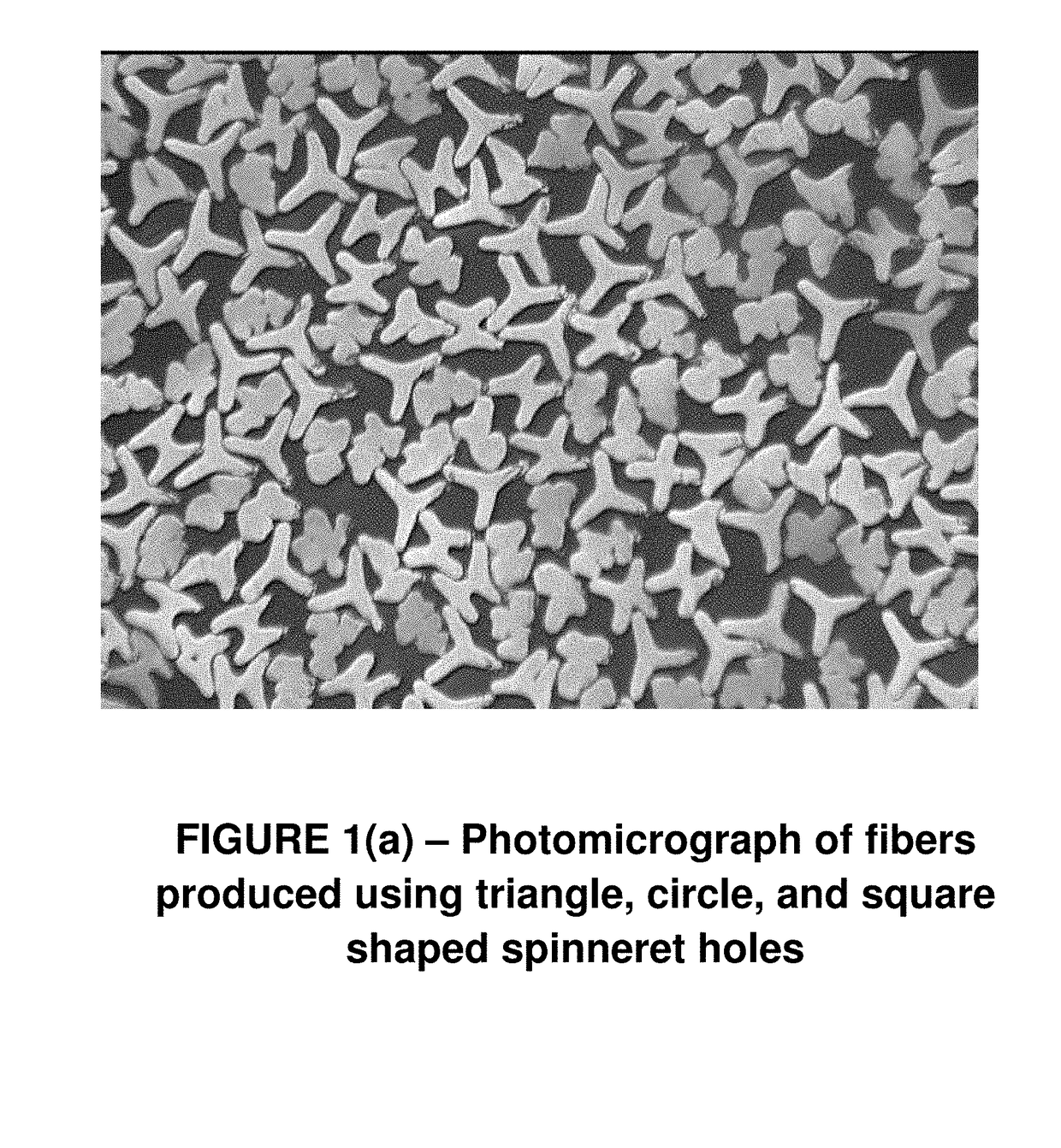
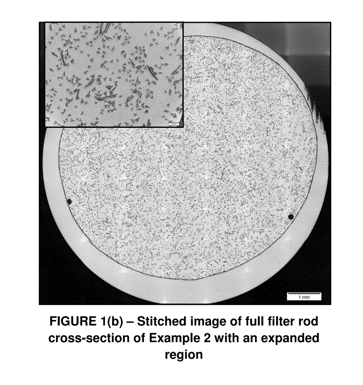
Fibers with chemical markers and physical features used for coding

a technology of chemical markers and physical features, applied in the field of identification fibers, can solve the problems of more overt solutions that are often susceptible to countermeasures such as destruction, modification, repackaging, or relabeling

Active Publication Date: 2018-01-09
EASTMAN CHEM CO
View PDF126 Cites 14 Cited by
  • Summary
  • Abstract
  • Description
  • Claims
  • Application Information

AI Technical Summary

Problems solved by technology

As stated above, there are many widely-used packaging and labelling taggants and anti-counterfeiting measures (ACMs) in many industries, but these more overt solutions are often susceptible to countermeasures such as destruction, modification, duplication, repackaging, or relabeling.

Method used


Image

  • Fibers with chemical markers and physical features used for coding
  • Fibers with chemical markers and physical features used for coding
  • Fibers with chemical markers and physical features used for coding

Examples


example 1

[0313]A 20 mL scintillation vial was charged with cellulose acetate (1.00 g) followed by HPLC grade acetone (11.38 mL) to give a mixture 10% (w / w) in solids. 100 μL of a 1.0 mg / mL stock solution of cesium (I) nitrate (0.68 mg / mL in cesium), prepared in a 9:1 acetone / water solution, and was added to the mixture to give a dope that was 68 ppm in cesium based on total solids. The vial was then placed on a continuous roller for a minimum of 16 hours or until a homogenous dope was formed. The dope was then poured into labeled culture dish bottoms (100 mm×20 mm) set in a transparent container with a cover. The solvent was allowed to slowly evaporate under cover for 5 hrs. The cover was then removed and the samples allowed to dry further under the draft of the fume hood for 1 hr. The samples were then removed from the dishes and submitted for ICP-MS analysis. The calculated spiked concentration of cesium, the measured concentration of cesium and the Recovery calculated as the percent measu...

examples 2-5

[0314]Example 1 was repeated to prepare four additional films, by linearly increasing the concentration by a factor of two in each film. The results are summarized in Table 1.

example 6

[0315]A 20 mL scintillation vial was charged with cellulose acetate (1.00 g) followed by HPLC grade acetone (11.38 mL) to give a mixture 10% (w / w) in solids. 100 μL of a 1.0 mg / mL stock solution of indium(III) chloride tetrahydrate (0.39 mg / mL in indium), prepared in a 9:1 acetone / water solution, and was added to the mixture to give a dope that was 39 ppm in Indium based on total solids. The vial was then placed on a continuous roller for a minimum of 16 hours or until a homogenous dope was formed. The dope was then poured into labeled culture dish bottoms (100 mm×20 mm) set in a transparent container with a cover. The solvent was allowed to slowly evaporate under cover for 5 hrs. The cover was then removed and the samples allowed to further dry under the draft of the fume hood for 1 hr. The samples were then removed from the dishes and submitted for ICP-MS analysis. The calculated spiked concentration of indium, the measured concentration of indium, and the % Recovery calculated as...


PUM


Abstract

Disclosed are fibers which contain identification fibers. The identification fibers can contain a one or more of chemical markers and one or more distinct features, or taggants, which may vary among the fibers or be incorporated throughout all of the fibers. The chemical markers and distinct features can be representative of specific supply chain information. The supply chain information can be used to track the fibers from manufacturing through intermediaries, conversion to final product, and / or the consumer. The disclosed embodiments also relate to the method for making and characterizing the fibers. Characterization of the fibers can include identifying chemical markers and distinct features and correlating the chemical markers and distinct features to manufacturer-specific taggants to determine supply chain information.

Description

CROSS-REFERENCES TO RELATED APPLICATIONS[0001]This application claims priority under 35 U.S.C. 119(e) to U.S. Provisional Application No. 62 / 018,222, filed Jun. 27, 2014; U.S. Provisional Application No. 62 / 018,182 filed Jun. 27, 2014; U.S. Provisional Application No. 62 / 018,192, filed Jun. 27, 2014; U.S. Provisional Application No. 62 / 105,017 filed Jan. 19, 2015; U.S. Provisional Application No. 62 / 105,011 filed Jan. 19, 2015; U.S. Provisional Application No. 62 / 105,022 filed Jan. 19, 2015; and U.S. Provisional Application No. 62 / 164,135 filed May 20, 2015 each of which is incorporated herein by reference in its entirety.TECHNICAL FIELD[0002]The disclosed embodiments relate to fibers comprising identification fibers. The identification fibers can contain a one or more of chemical markers and one or more distinct features, or taggants, which may vary among the fibers or be incorporated throughout all of the fibers. The chemical markers and distinct features can be representative of ...

Claims


Application Information

Patent Timeline
Patent Type & Authority Patents(United States)
IPC IPC(8): G01N30/02A24D3/00A24D3/06G01N33/36G07D7/12D01F2/28D01F1/10D01F1/04D01D5/253G01N30/72G01N24/08G01N23/00G01N21/73G01N21/64G01N21/31A24D3/04
CPCG01N30/02A24D3/04A24D3/063D01D5/253D01F1/04D01F1/10D01F2/28G01N21/31G01N21/6428G01N21/73G01N23/00G01N24/087G01N30/72G01N33/36G07D7/12A24D3/00G01N2021/6439G07D7/14G07D7/2033B41M5/267
Inventor GAYNOR, SCOTT GREGORYMCLEOD, ANDREW ERVINWILSON, STEVEN ANTHONYCOLLAZO, HUMBERTORENFRO, LARRY WAYNESALYER, LYDIA JUANITASTEACH, JEREMY KENNETHRODIG, MICHAEL JOHNSEILER, BRIAN DOUGLASHORTON, JONATHANTATUM, CLARISSA
Owner EASTMAN CHEM CO
Why Eureka
Try Eureka