Internal combustion heating device of coal pyrolyzing furnace

a heating device and combustion technology, applied in the direction of combustible gas production, solid fuel combustion, lighting and heating apparatus, etc., can solve the problems of low productivity, no complete technique for exporting, recovering, purifying and utilizing raw gas, and discontinuous production, so as to avoid direct discharge of dry quenching exhaust and atmosphere pollution, increase the burning capacity, and reduce the coking cost

Active Publication Date: 2018-01-30
SHANXI XINLI ENERGY TECH
View PDF1 Cites 0 Cited by
  • Summary
  • Abstract
  • Description
  • Claims
  • Application Information

AI Technical Summary

Benefits of technology

[0013]According to the present invention, the upper internal sub flame path section and the lower internal sub flame path section as well as the internal main flame path utilize the high-temperature combustible exhaust generated by dry quenching for gas refilling, burning and heating, so as to avoid directly discharging dry quenching exhaust and atmosphere pollution. The middle internal sub flame path section utilizes the clean coal gas obtained by purifying and recycling the raw gas for burning, gas refilling and heating, so as to increase an insufficient burning capacity of the high-temperature combustible exhaust, in such a manner that sufficient temperature and heat are provided for coal pyrolyzing and carbonizing. There is no need for extra heating equipment, which is eco-friendly and economic, and lowers a coking cost.

Problems solved by technology

Conventionally, coal pyrolyzing furnaces (coke ovens) on the market usually utilize intermittent coking, wherein the proportion of inputting coal, dehydration, coal feeding, preheating, carbonization, coke modification, dry quenching, etc. are relatively independent, which results in discontinuous production and low productivity.
There is no complete technique for exporting, recovering, purifying and utilizing the raw gas.

Method used


Image

  • Internal combustion heating device of coal pyrolyzing furnace
  • Internal combustion heating device of coal pyrolyzing furnace
  • Internal combustion heating device of coal pyrolyzing furnace

Examples


Embodiment Construction

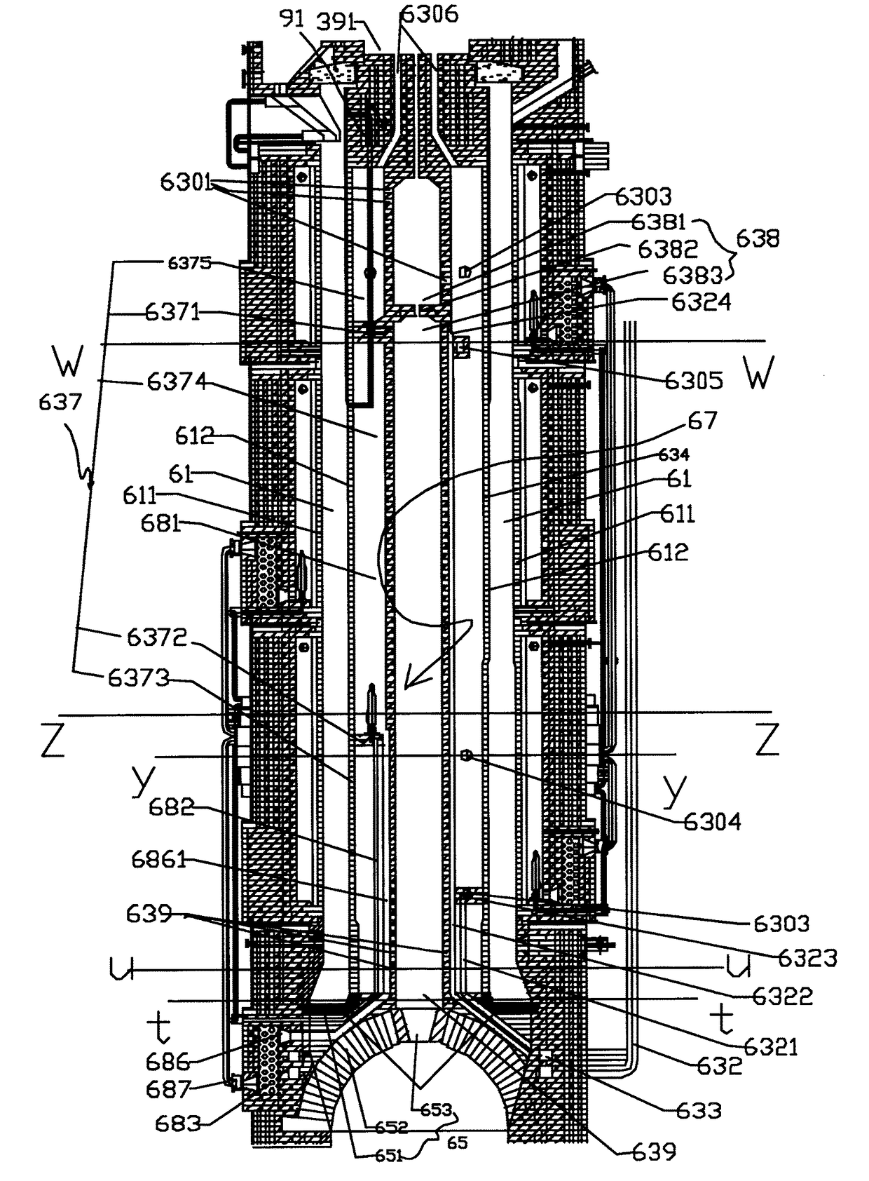
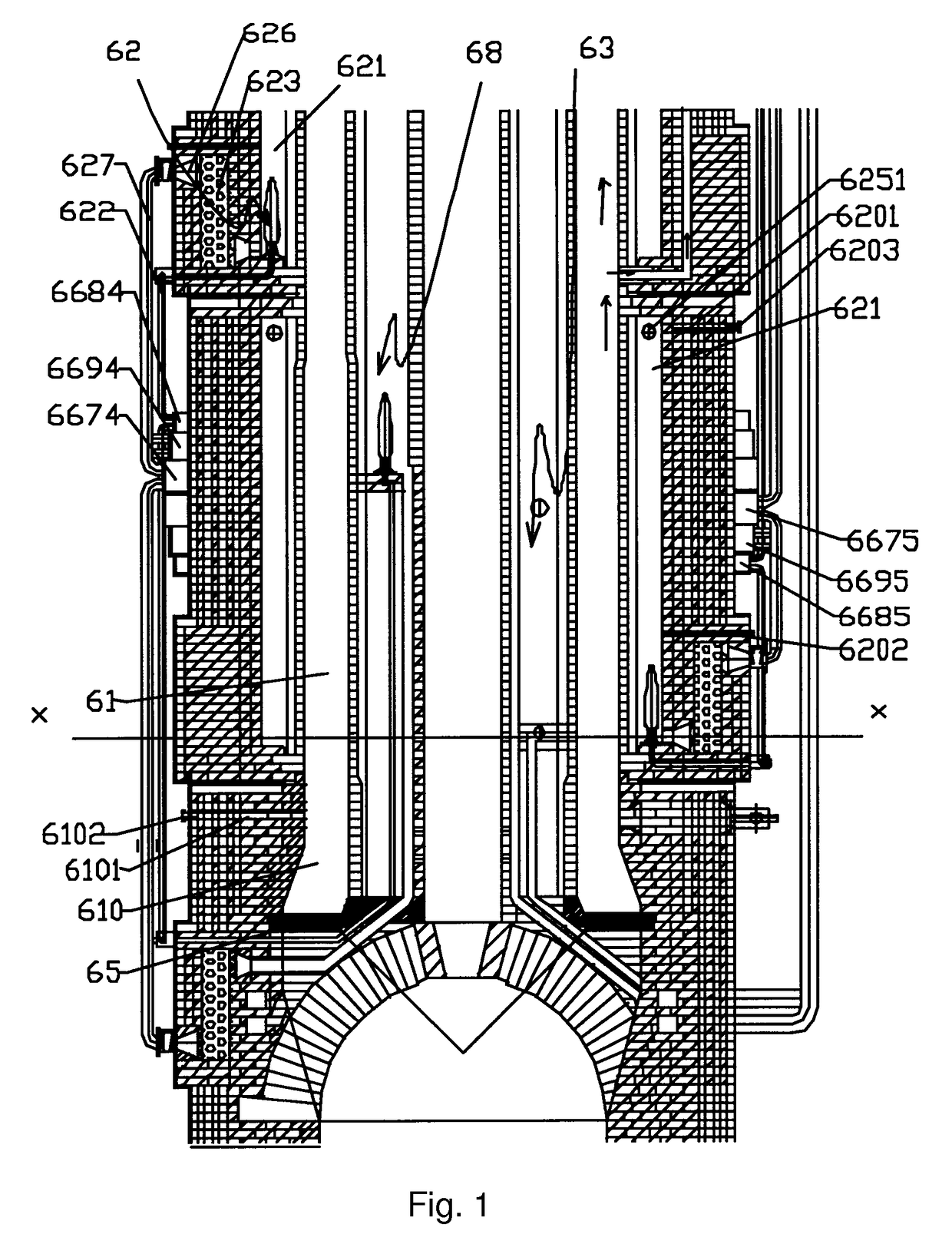
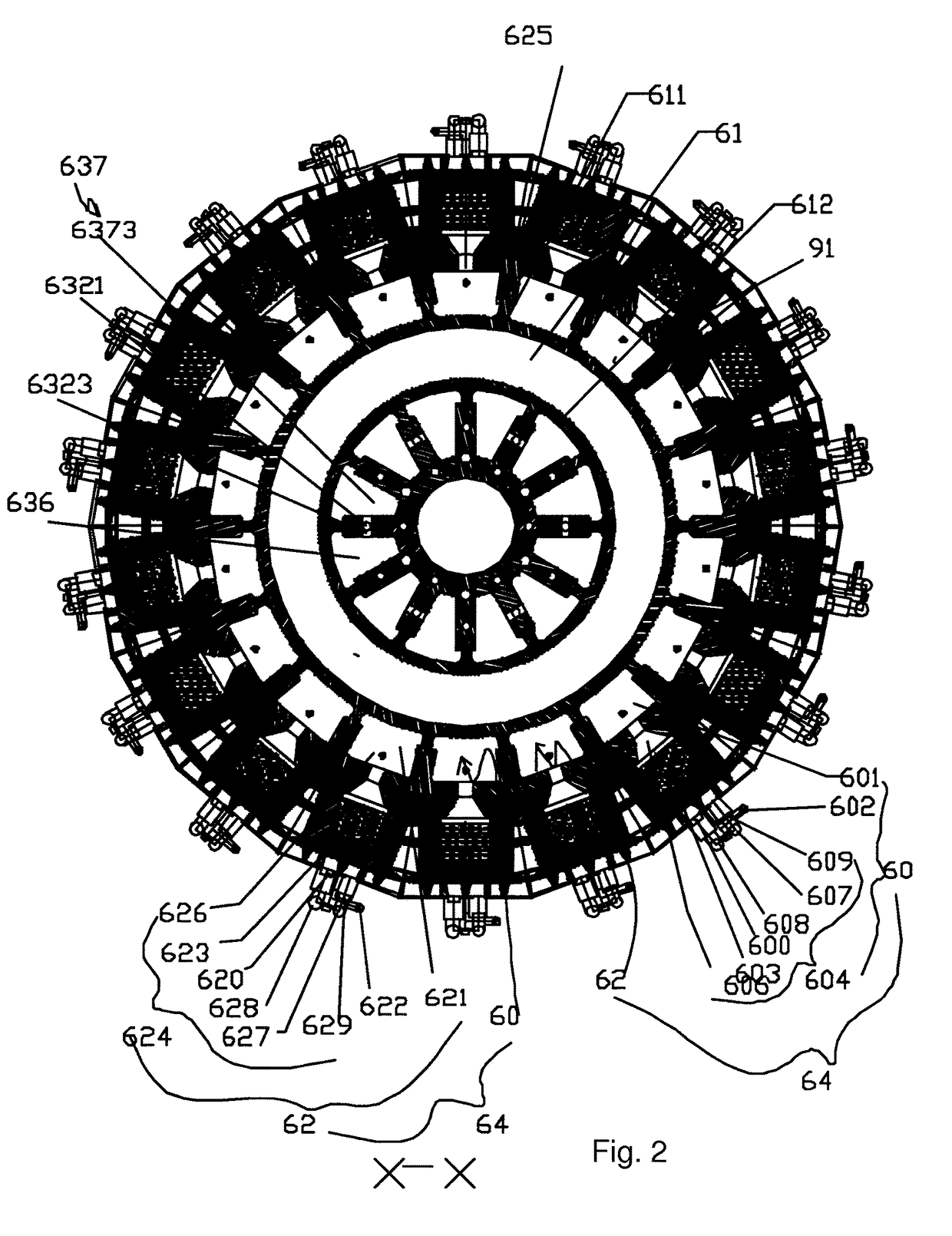
[0031]A preferred embodiment of an internal combustion heating device of a coal pyrolyzing furnace of the present invention is described in detail in Section I, Part IV.

[0032]Part I: Proportion and Preparation of Inputting Coal

[0033]Five different kinds of coal are selected, which are gas coal, fat coal, coking coal, one-third coking coal and lean coal. The five different kinds of coal are mixed and then screened and crashed for forming the inputting coal. Of course, other proportions are also adaptable to the coal pyrolyzing furnace of the present invention. Therefore, inputting coal powder of the coal pyrolyzing furnace of the present invention is not limited.

[0034]Part II: Dehydration of Inputting Coal

[0035]By pre-dehydrating the inputting coal of the coal pyrolyzing furnace through a dehydration device, energy is saved.

[0036]Part III: Feeding, Pre-Heating, Regulating and Cooling of Inputting Coal

[0037]After transporting, a temperature of dehydrated inputting coal usually drops t...


PUM

PropertyMeasurementUnit
temperatureaaaaaaaaaa
heataaaaaaaaaa

Abstract

An internal combustion heating device of a coal pyrolyzing furnace includes a coke quenching exhaust heater and at least one set of a third gas heater and a fourth gas heater with equal structures and associated with each other; wherein the coke quenching exhaust heater comprises an internal flame path, a first air supply tube, a second air supply tube, a central annular wall and a central path, wherein an internal flame path is divided into at least one set of an internal main flame path and an internal sub flame path, the central annular wall inside the internal loop wall of the carbonizing room and at least one the internal flame path isolating wall; the internal sub flame path is divided into an upper section, a middle section and a lower section.

Description

CROSS REFERENCE OF RELATED APPLICATION[0001]This is a U.S. National Stage under 35 U.S.C. 371 of the International Application PCT / CN2013 / 080817, filed Aug. 5, 2013, which claims priority under 35 U.S.C. 119(a-d) to CN 201210278088.4, filed Aug. 6, 2012.BACKGROUND OF THE PRESENT INVENTION[0002]Field of Invention[0003]The present invention relates to a gas combustion heating device, and more particularly to a device which utilizes gas generated by dry quenching and pyrolyzing of a coal pyrolyzing furnace for burning and heating.[0004]Description of Related Arts[0005]Conventionally, coal pyrolyzing furnaces (coke ovens) on the market usually utilize intermittent coking, wherein the proportion of inputting coal, dehydration, coal feeding, preheating, carbonization, coke modification, dry quenching, etc. are relatively independent, which results in discontinuous production and low productivity. In addition, raw gas produced during coal pyrolyzing comprises many useful ingredients, such ...

Claims


Application Information

Patent Timeline
Patent Type & Authority Patents(United States)
IPC IPC(8): C10J3/20C10B53/04C10B3/00C10B3/02C10B31/02C10B39/02C10B57/00C10B33/12F23B30/00F23C6/04F23C9/06C10B21/10
CPCC10J3/20C10B3/00C10B3/02C10B21/10C10B31/02F23C9/06C10B39/02C10B53/04C10B57/005F23B5/04F23C6/04C10B33/12
Inventor WANG, XINMINWANG, WENBU
Owner SHANXI XINLI ENERGY TECH
Why Eureka
Try Eureka