Precision positioning device and stage incorporating a globoid worm and its manufacture

a technology of positioning device and worm, which is applied in the direction of worms, gearing, hoisting equipment, etc., can solve the problems of globoid worm drives, high manufacturing cost and sensitivity of enveloping pinion to the axial location, and the inability to manufacture new custom high precision parts

Active Publication Date: 2018-01-30
MAURO COMML IND OF VERO BEACH LLC
View PDF10 Cites 15 Cited by
  • Summary
  • Abstract
  • Description
  • Claims
  • Application Information

AI Technical Summary

Benefits of technology

[0043]A further object and benefit is the ability of the right angle drive to take full advantage of an integrated bearing in rotational stages.

Problems solved by technology

The problem for rotational stages is making a full line of standard and custom sizes without the prohibitive expense of new custom high precision parts for each variation.
The most commonly cited disadvantages concerning conventional implementations of globoid worm drives include higher manufacturing cost and sensitivity of the enveloping pinion to the axial location.

Method used


Image

  • Precision positioning device and stage incorporating a globoid worm and its manufacture
  • Precision positioning device and stage incorporating a globoid worm and its manufacture
  • Precision positioning device and stage incorporating a globoid worm and its manufacture

Examples


first embodiment

[0073]Combination of Globoid Worm and Star Gear / Spur Gear Subassemblies

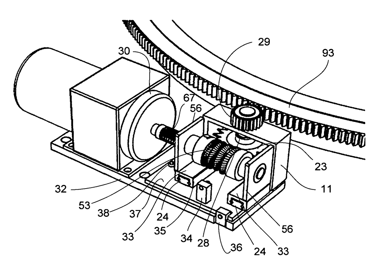
[0074]In a first embodiment, the device comprises two subassemblies, a globoid worm subassembly and a star gear-spur gear subassembly, respectively. Reference is made to FIG. 3, an exploded diagram of the subassemblies. This figure does not depict the gear preload mechanisms; the subassemblies interface with each other through these preload mechanisms as will be described below. The star gear—spur gear assembly 5 comprises a star gear shaft 19 retained in gear mount 11. The star gear 23 is affixed to shaft 19 by set screw 21. The locking washer 17 retains the gear shaft axially (longitudinally). At the end of shaft 19, a drive spur gear 29 is affixed to the end of shaft 19 by a mounting set screw 25 in the hub 27 of drive spur gear 29. The star gear 23 is caused to engage the globoid worm 53 (shown in the globoid worm assembly 3) by a first preload mechanism and the drive spur gear is caused to engage a stage gea...

second embodiment — first embodiment

[0077]Second Embodiment—First Embodiment with Addition of Drive Subassembly

[0078]In a second embodiment, the device comprises three subassemblies, specifically comprising a globoid worm subassembly, a star gear-spur gear subassembly, and a drive subassembly. With respect to FIG. 4A, the drive subassembly comprises the drive motor 30 and flexible coupling 67. Within the scope of this disclosed right angle drive, an alternative drive subassembly may comprise a manual actuator such as a thumbwheel, or mechanical interfaces to various other power or actuation sources well known in the prior art, such as piezoelectric, magnetostrictive, hydraulic, etc.

third embodiment — second embodiment

[0079]Third Embodiment—Second Embodiment with Addition of Stage Gear Subassembly

[0080]In a third embodiment, the device comprises four subassemblies, specifically, these are: a globoid worm subassembly, a star gear-spur gear subassembly, a drive subassembly, and a stage gear subassembly. The stage gear subassembly is configured after the fashion of the integrated bearing concept disclosed in U.S. Patent Application Number US 2011 / 0317951, which is incorporated herein by reference thereto. The advantages of this bearing concept over conventional bearings are many and enumerated in the aforementioned application.

[0081]The primary objects and applications of the integrated bearing concept are (1) a dedicated high precision, low to moderate load and low to moderate speed rotational positioning table or stage without the typical tradeoffs encountered by using conventional standard bearings that were fundamentally designed for other applications, and (2) the simplified customization and m...


PUM


Abstract

The device is a precision motion right angle drive for use with linear and rotary stages which employs a combination of globoid worm and small diameter star gear. Coaxial with the star gear, on the same shaft, is a spur gear which drives the rotary stage gear or a linear rack. The thin star gear achieves meshing accuracy with the globoid worm permitting a large tooth angle for direct preloading without jamming. This gear combination eliminates backlash, allows a low gear ratio for low globoid worm speed, and enables the use of an ordinary spur gear to engage the stage gear without backdrive or backlash. Further, it allows for gear contact area to compensate for the thinness of the star gear. An embodiment including an integrated bearing rotary stage permits flexibility of application and avoidance of need for custom bearing designs by achieving high motion precision at low cost.

Description

CROSS REFERENCE TO RELATED APPLICATIONS[0001]This application claims the benefit of provisional patent application Ser. No. 62 / 070,266 filed 2014 Aug. 19.BACKGROUND[0002]Precision positioning stages, both linear and rotary, are used for laboratory and industrial applications including fiber optic and optical alignment systems.[0003]Prior art technologies include means to achieve precision linear or rotational motion using either open-loop or closed-loop methodologies. In the context of right angle drives, of relevance are means that achieve precision motion while converting rotation along one axis into rotation along a second axis, orthogonal to the first. Application to linear output motion, concerns means of converting precise rotation about a first axis into precise translation along a second axis, orthogonal to the first. Various drive systems employed for stage motion include lead screws, recirculating ball screws, worm drives, gearboxes, and flexible shaft couplings. Prime mov...

Claims


Application Information

Patent Timeline
Patent Type & Authority Patents(United States)
IPC IPC(8): F16H1/16F16H55/22F16H1/20B23F13/06
CPCF16H1/203F16H55/22B23F13/06F16H2057/0213F16H37/041F16H57/12F16H1/16F16H2057/0222F16H2057/127
Inventor MAURO, GEORGEDAVIS, DENNIS WILLARD
Owner MAURO COMML IND OF VERO BEACH LLC
Why Eureka
Try Eureka